Pressure Reuglator
Air Pressure Regulator are found in many common home and industrial applications. For example, in pneumatic automation systems to regulate compressed air. In each of them, the pressure regulator provides the same function. Pressure regulators reduce a supply (or inlet) pressure to a lower outlet pressure and work to maintain this outlet pressure despite fluctuations in the inlet pressure. The reduction of the inlet pressure to a lower outlet pressure is the key characteristic of pressure regulators.
Table of Contents
What’s The Air Pressure Regulator?
The Structure of The Typical Air Pressure Regulator.
How Many Types Air Regulator There Are ?
Overflow mode and Non-overflow mode.
High pressure regulators
Pilot operated regulators
A single-stage regulator
A double-stage regulator
General purpose regulators
Low pressure regulators
In a vacuum or compound regulator
What is the difference between the regulator and the pressure cut-in switch?
How To Choose a Air Pressure Regulator?
Operating pressure
Flow requirement
Operating fluid and environment
Operating temperature
Size & Weight
Select The Right Gauge!
How to install a compressor regulator?
List of pressure units for conversion.
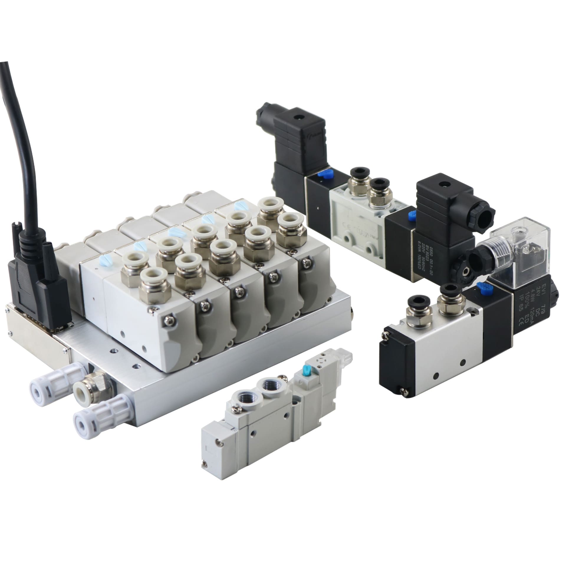
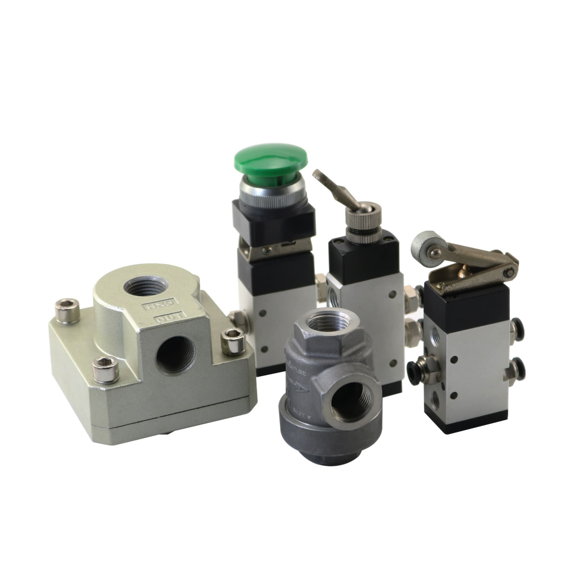
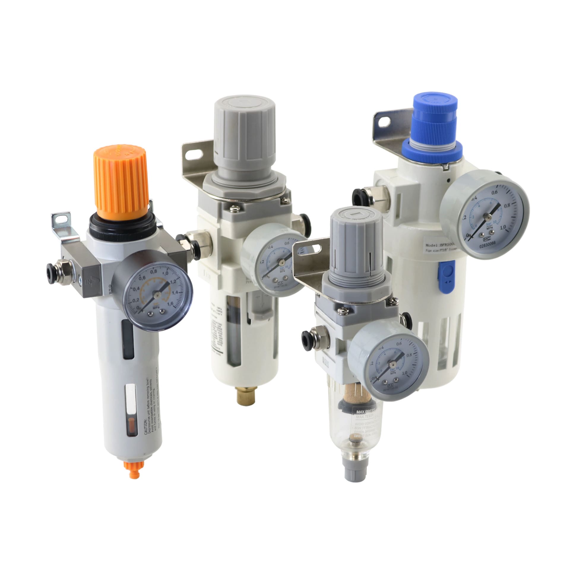
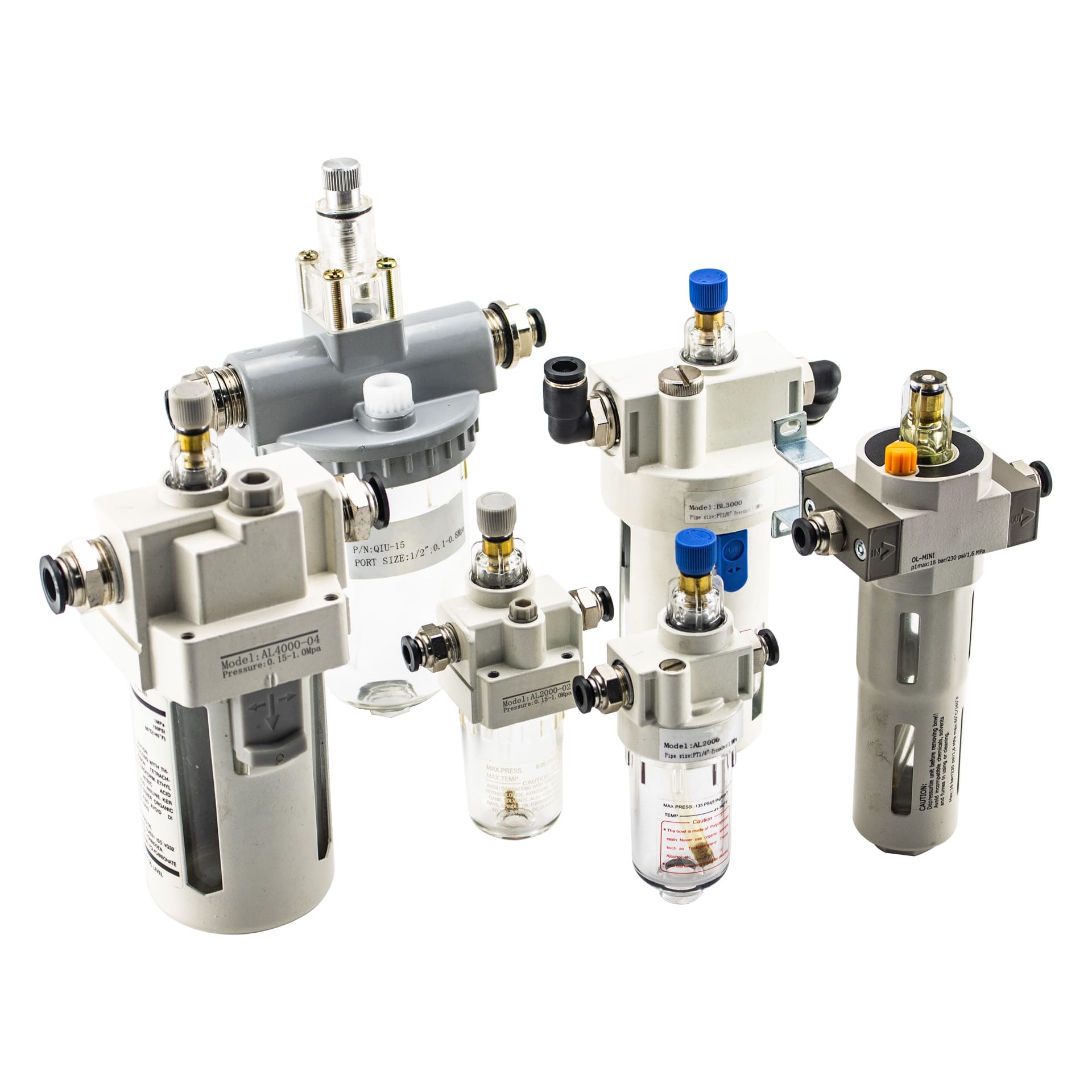
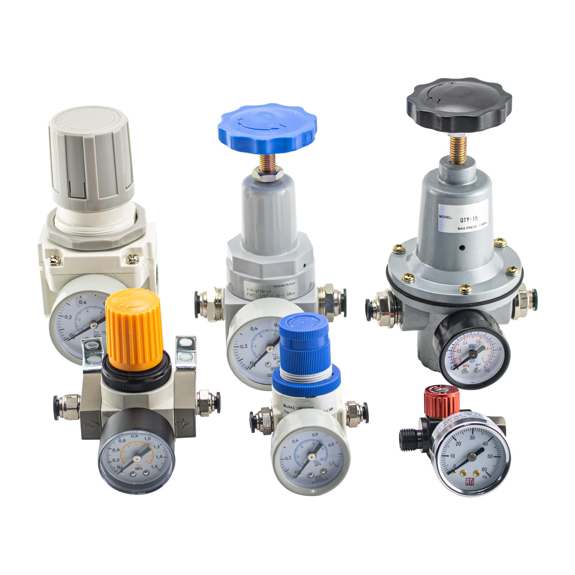
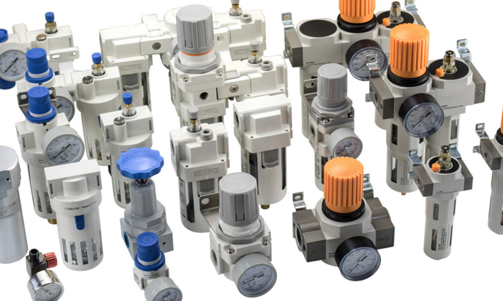
Our Air Pressure Regulators.
What’s The Air Pressure Regulator?
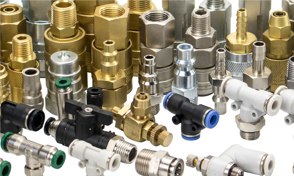
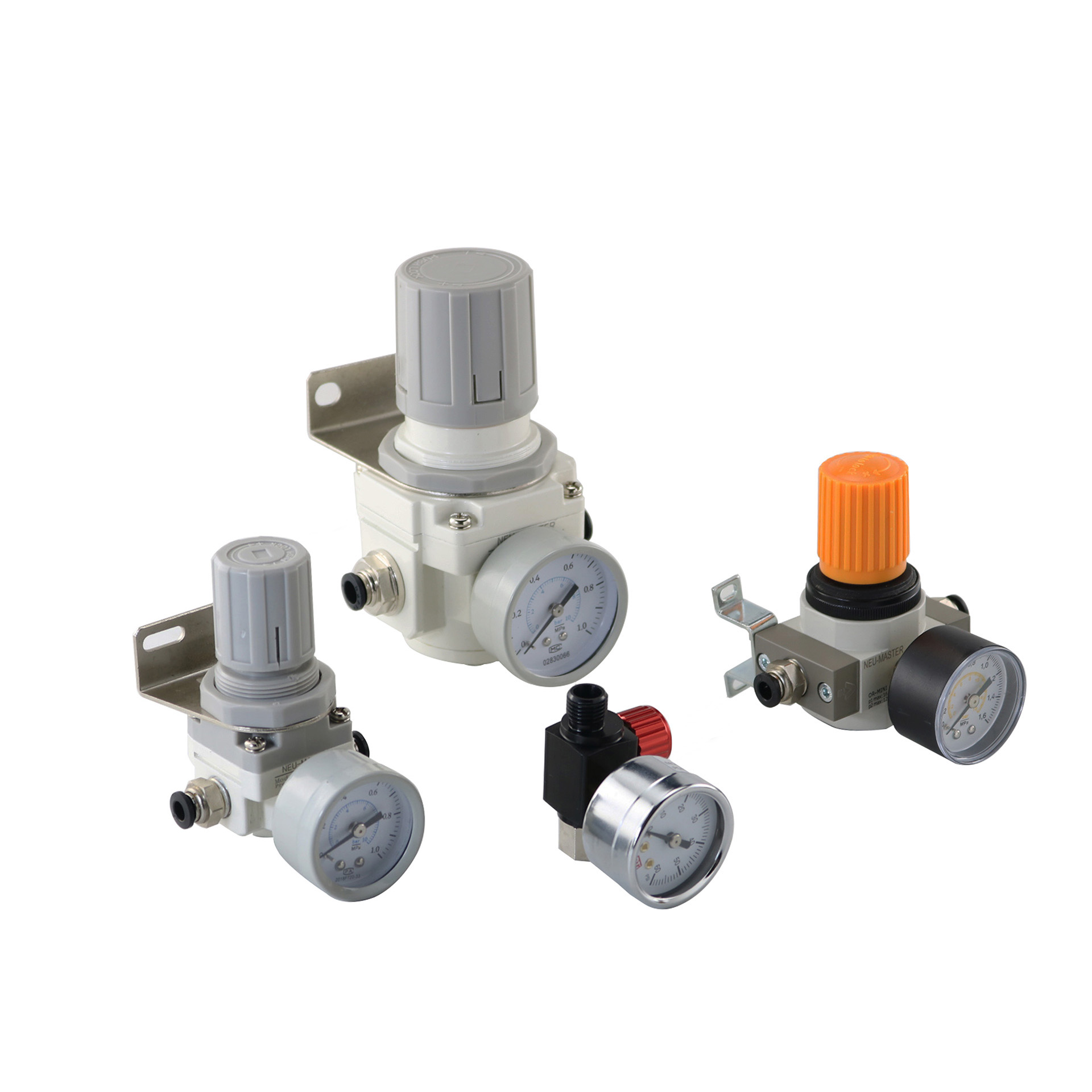
Air pressure regulators is a device which we generally adopt for reducing compressed air pressure levels to a specified value though adjust the knob on the regulator. It will keep the outlet pressure in the set point unless the inlet pressure lower than the set value. Be with ultimately lowers costs and provides an element of safety. Additionally, the pneumatic equipment often has optimum air pressure value that we needs to monitored carefully in order to achieve reliable performance. At Dg-Pnetic, we have a wide range of air pressure regulators. They range from general purpose units covering everyday industrial applications to more specialised precision regulators.
The structure of the typical air regulator
A typical pressure regular consists of the following elements:
1. A pressure reducing element such as a poppet valve.
2. A loading element to apply necessary force to the reducing element such as a spring, piston actuator or a diaphragm actuator.
3. A sensing element such as a diaphragm or a piston
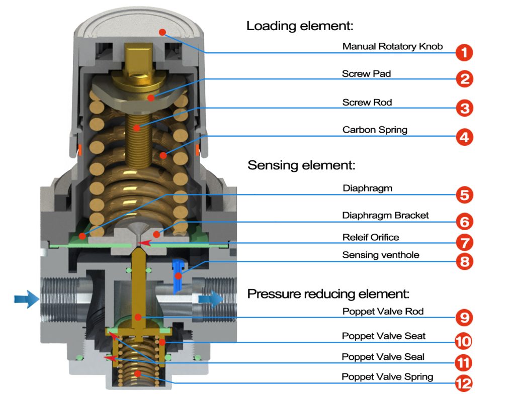
Loading element
The loadig element is a device to force the sensing element to open a valve. Normally it’s a strong spring! The amount of spring force is variable which determines the force of outlet pressure obtained.
The sensing element
Normally, we adopt the pistons or diaphragm as the sensing element.
In the high pressures, rugged applications and applications where wider tolerances on the outlet pressure are acceptable, we tend to adopt the piston sensing element. But they are sluggish due to friction between the pinion sealing and regulator body.
Diaphragm type of sensing element is suitable for the higher accuracy regulator. Normally, we made it of elastomer or a thin disc type of material which is sensitive to changes in pressure. As the diaphragms tend to have lower friction than piston type designs, so they provide a higher sensing area, for a given regulator size.
Pressure reducing element
Spring loaded poppet valves are common pressure reducing element. Poppet valves have elastomeric sealing in regular applications and a thermoplastic sealing in high pressure applications. This seals the valve seating against any gas or fluid squeezing through. The combined force generated by the sensing element and loading element control the poppet valve to open the valve and let the medium flow from inlet to outlet or shut down.
How does the pressure regulating valve work?
The Process Of Turning Up The Outlet Pressure
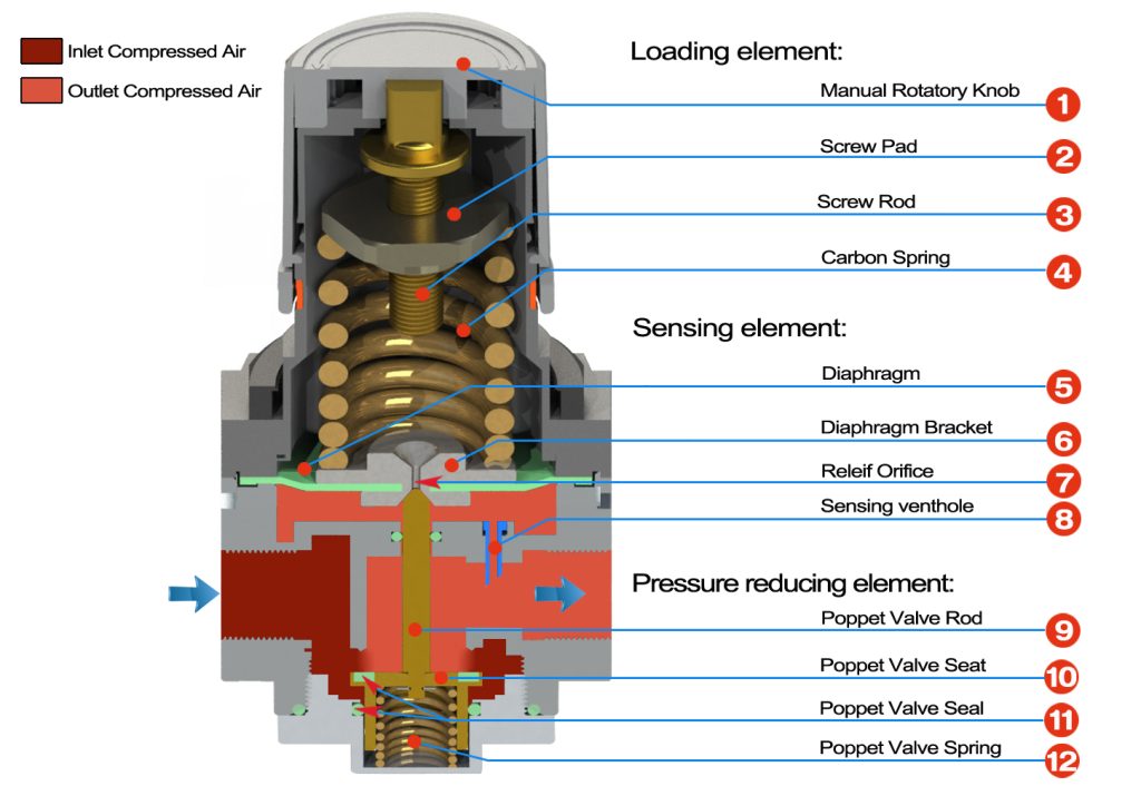
First Step: Turn the Rotatable Knob ① clockwise, (Normally, turning clockwise is to increase the outlet pressure), then the knob will drive the Screw Rod ③ rotating together.
Second Step: The Screw Rod actuate the the Screw Pad ② moving downward to press the Carbon Steel Spring ④.
As the Thread Pad ② be with the hexagonal shap outer edge, so it well fitted with the internal cavity of the die casting regulator body. Thus it will move down under the torsion force but not rotate together.
Third Step: The Carbon Spring ④ press the Diaphragm Bracket ⑥ to push down the Poppet Valve Rod ⑨, furtherly open the poppet valve (Pressure Reducing Element).
Fouth Step: The compressed air get through the poppet valve and pass into the outlet pipe, and meaning time into the Sensing Element cavity through the Sensing Venthole ⑧.
Fifth Step: The compressed air in the Sensing Element cavity push the Diaphragm ⑤ upward. And react on the Carbon Steel Spring ④ by the Diaphragm bracket ⑥. Therefore, the poppet valve rod move up, and poppet valve tend to close. The trend lead to the outlet pressure reducing, moreover the press under the Diaphragm lower than Carbon steel spring. So it will press downward again. Then system will repeat the Third to Fifth Step in theory, finally get a balance point at higher outlet pressure.
Interpretation: the open of poppet valve (Pressure Reducing Element) is a resault of the combined force which generated by the sensing element and loading element, that overcomes the spring force.
The Process Of Turning Down The Outlet Pressure

First Step: Turn the Rotatable Knob ① anticlockwise, (Normally, turning anticlockwise is to reduce the outlet pressure), meaning time knob will drive the Screw Rod ③ rotating together.
Second Step: The Screw Rod drive the the Screw Pad ② moving upward to release the Carbon Steel Spring ④.
How Many Types Air Regulator There Are ?
As all of the regulator share the same working principle, so it’s difficult to classify pressure regulator accurately. But we still classified them according to different usage conditions, pressures range, or accuracy etc.
According to the usage conditions, we classify the regulator into Overflow mode and Non-overflow mode.
We always adopt the overflow mode in the compressed air system or harmless gas regulation. That’s meaning once we adjust the outlet pressure to zero(Atmospheric pressure), the compressed air may relief from the regulator if there is no consumption ! But in lots of applications, the gas is toxic, explosive, or corrosive, if the gas relief from the regulator, may result in disaster. So gas still stay in the pipeline till they are consumed in the normal way.
High pressure regulators
Are usually rate for maximum 350 bar inlet pressure, with an outlet pressure up to 3-12bar, depending on the materials we used in construction.
A single-stage regulator is ideal for relatively small reduction in inlet pressure. They are not suitable where there are large fluctuations in inlet pressure or flow rates.
A double-stage regulator is the most commonly type in the high pressre cylinders application. Two-stage regulators are two single-stage regulators combined in one, it will operates to reduce the pressure progressively in two stages. The first stage, which we preset, reduces the pressure of the supply gas to an intermediate stage. And gas at that pressure passes into the second stage. Two-stage regulators have two safety valves for added protection. They offer a finer adjustment of pressure over the recommended range.
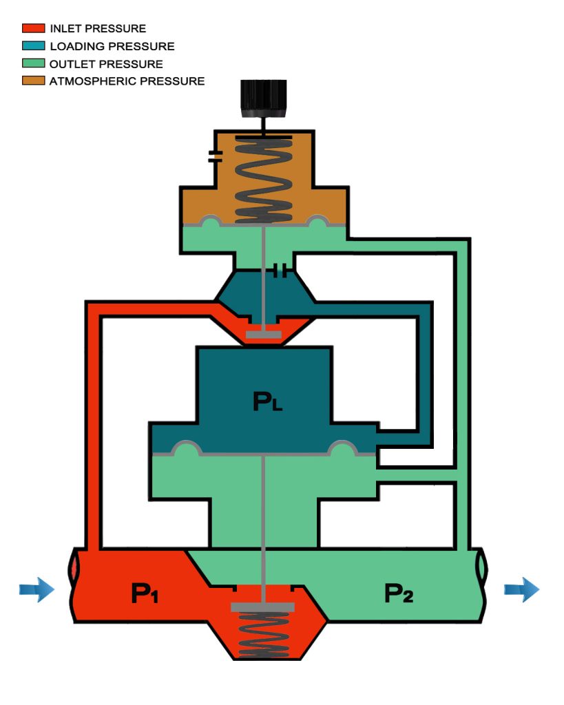
Pilot operated regulators
Using gas pressure instead the compression spring as the loading element. This allows control from a extreme position, where generate a force greater than mechanical load spring. Also they exhibit better flow characteristics.
These regulators are ideal for applications with large variation in flow rates and fluctuations in inlet pressure. Such as the decreasing inlet pressure conditions that normally occur with natural gas supplied in cylinders, natural gas pipeline,etc. It also provides precise pressure control. This type of regulator is generally pilot operate device with Overflow orifice or Non-overflow desgin.
The work principle of Pilot operated regulators
General purpose regulators : we designe it for typical industrial use. These generally operates only above atmospheric pressure. The air pressure regulator is the typical model.
Low pressure regulators have special design characteristics for precise control of pressures typically below 15 – 20 psi.
In a vacuum or compound regulator, also known as an absolute pressure regulator, we desige the regulator to control fluid below atmospheric pressure.
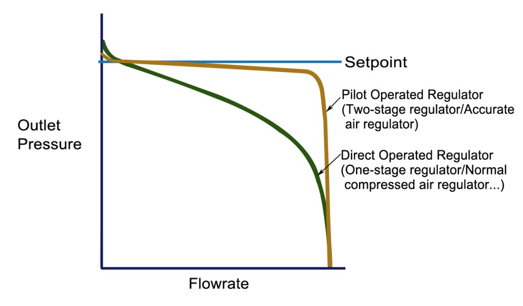
What’s The Accuracy Of The Air Regulator?
The accuracy: we indicate it by charting outlet pressure versus flow rate. The right graph shows the drop in outlet pressure as the flow rate increases; a phenomenon known as outlet pressure droop. We define the pressure regulator accuracy as how much pressure droop the device exhibits over a range of flow rate; less droop equals greater accuracy.
What is the difference between the air regulator and flow control valve?
The main difference between a pressure regulator and a flow control valve is their focus. Pressure regulators focuse on maintaining constant pressure, whereas flow control valves focuse on maintaining a constant flow rate. The choice between them depends on the specific requirements of the system in question, such as the desired flow rate or the maximum operating pressure.
How To Choose a Air Pressure Regulator?
There are several factors to consider in choosing the correct Regulator for an application.
Operating pressure
What is the operating pressure at the input port and the required pressure at the output? What is the precision in control of the output pressure?
Flow requirement
As said above, a pressure regulator is not a flow controller, but clearly, there is a relationship between the two. All manufacturers will provide a graph showing flow as a function of pressure and it is important to make sure the required flow range is in a linear part of the line.
Operating fluid and environment
Whilst we focus on compressed air as the medium, there are many applications with other gases; it is important that particularly the seals are resistant to any non-inert medium. The environment will impact choice; for example, in a hostile environment, it is likely that pilot operation will be required, so adjustments can be made remotely.
Operating temperature
Materials chosen will be different for applications outside in the arctic circle, compared to a furnace!
Size and weight – some applications, for example medical, may have restrictions on these physical parameters.
Size & Weight
In many high technology applications space and weight are the import factors. Some manufactures specialize in miniature components and should be consulted. Material selection, particularly the regulator body components, will impact weight. Also carefully consider the port (thread) sizes, adjustment styles, and mounting options as these will influence size and weight.
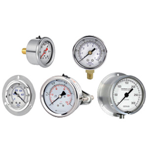
Select The Right Gauge!
When we select the gauges for a regulator or other applications, we should consider the regulator’s inlet pressure and designed outlet pressure. Two of the major points are accuracy and safety.
Accuracy:
Virtually all applications using gases require some degree of accuracy to ensure proper and safe performance. A common comparison would be the accuracy a driver would demand from the speedometer in an automobile he or she was operating. In the industrial or welding gas industry we look to an accuracy like that suggested by the Compressed Gas Association (CGA) in their E-4 standard for gas pressure regulators. In standard gauges most commonly used in our industry, Grade B are accurate within 2% – 3% of the gauge span or gauge face reading, depending somewhat where on the gauge face the pressure is read. See the drawing example using a 100 PSIG gauge.
Safety:
There are an innumerable number of choices in our industry of gauge pressure ranges to choose from when selecting a gauge for a regulator or other use. The trick is to choose a gauge that provides the reading accuracy required while still providing durable and safe operation. Again, referring to standards like CGA E-4 1994 (5.7.2) we select gauges so that the maximum operating pressure to which shouldn’t greater than 80% of the gauge range. We also take into consideration all other factors that may affect pressures such as those related to temperature, gas mode, etc.
How to install a compressor regulator
Step 1:
Begin by connecting the pressure source to the inlet port and the regulated pressure line to the outlet port. If there is no mark beside the port, check with the manufacturer to avoid incorrect connections. In some designs, damage can occur to the internal components if the supply pressure is mistakenly supplied to the outlet port.
Step 2:
Before turning on the supply pressure to the regulator, back off the adjustment control knob to restrict flow through the regulator. Gradually turn on the supply pressure so as not to “shock” the regulator with a sudden rush of pressurized fluid. NOTE: Avoid turning the adjustment screw all the way into the regulator because, in some regulator designs, the full supply pressure will get into the outlet port directly.
Step 3:
Set the pressure regulator to the desired outlet pressure. When the regulator is non-over-flow model, it will be easier to adjust the outlet pressure if fluid is flowing rather than “dead ended” (no flow). Never vent fluid by loosening fittings, as the action may lead to injury.
With a over-flow style regulator, excess pressure will be automatically vented to atmosphere from the regulator when the knob is rotated to lower the output setting. For this reason, do not use over-flow style regulators with flammable or hazardous fluids. Be sure the vent the excess fluid safely and in accordance with all local, state and federal regulations.
Step 4:
To obtain the desired outlet pressure, make the final adjustments by slowly increasing the pressure from below the desired set point. Setting the pressure from below the desired value is the right action. If you overshoot the set point while setting the pressure regulator, back off the set pressure to a point below the set point. Then, again, gradually increase the pressure to the desired set point.
Step 5:
Cycle the supply pressure on and off several times while monitoring the outlet pressure to confirm the regulator is consistently returning to the set point. Additionally, we should cycle the outlet pressure on and off to ensure the pressure regulator returns to the desired set point. Repeat the pressure setting sequence if the outlet pressure does not return to the desired setting.
List of pressure units for conversion
pascal [Pa]
kPa = 1000 Pa
bar = 100000 Pa=100kPa
bar = 14.5psi
psi = 6894.75[Pa]
1Mpa=10Bar=145psi=1000000Pa=1000Kpa