
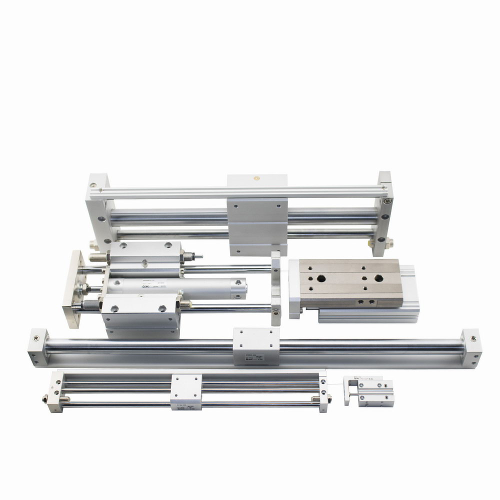
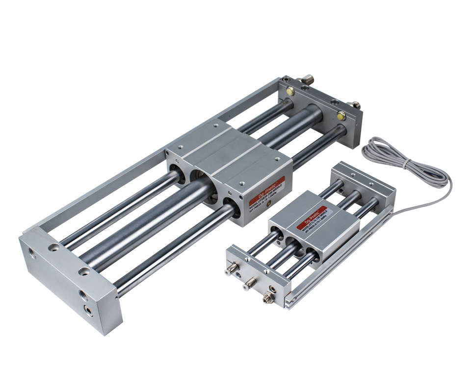
 A rodless cylinder is a pneumatic actuator that moves a load in a straight line using compressed air—without an external piston rod. Instead, the load is moved in tandem with the internal piston via a link block or carrier that travels along the length of the cylinder.
This design is especially beneficial when the required stroke is long. Traditional cylinders with piston rods can suffer from rod bending or deflection under extended strokes. By eliminating the external rod, rodless cylinders offer a more stable and space-efficient solution.
 Where Are Rodless Cylinders Used?
Rodless cylinders are ideal for applications where installation space is limited but long travel is needed. Common use cases include:
Pushing or transporting workpieces
Mechanism opening and closing
Vertical or horizontal lifting
Automated door operation
Linear conveyance of materials
 How Do Rodless Cylinders Work?
Unlike traditional cylinders, rodless versions connect the piston directly or indirectly to the actuator. The internal piston’s movement is transferred to the external carriage or slide, which carries the load along the cylinder’s axis.
This design eliminates the need for rod extension and retraction outside the cylinder body, allowing the device to remain compact yet powerful.
Bore Size(mm): 6, 10, 15, 20, 25, 32, 40
Action: Double Acting
Working Pressure:
 0.18~0.70Mpa (26Psi~100Psi) (1.8~7Bar)
Working Temperature ℃: -10~60℃. (No Freezing)
Cushion Type: Rubber Buffer or Hydraulic Buffer
Stroke Tolerance: 0-250: 0-1.0mm; 251-1000: 0-1.4mm; 1001-… : 0-1.8mm.
Piston Speed: 50~1000mm/s
Standard Stroke(mm): 50 100 150 … 1000mm
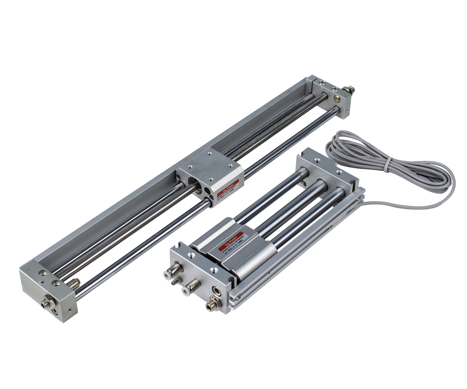
Bore Size(mm): 6, 10, 15, 20, 25, 32, 40
Action: Double Acting
Working Pressure: 0.18~0.70Mpa (26Psi~100Psi) (1.8~7Bar)
Working Temperature ℃: -10~60℃. (No Freezing)
Cushion Type: Rubber Buffer or Hydraulic Buffer
Stroke Tolerance: 0-250: 0-1.0mm; 251-1000: 0-1.4mm; 1001-… : 0-1.8mm.
Piston Speed: 50~1000mm/s
Standard Stroke(mm): 50 100 150 … 1000mm
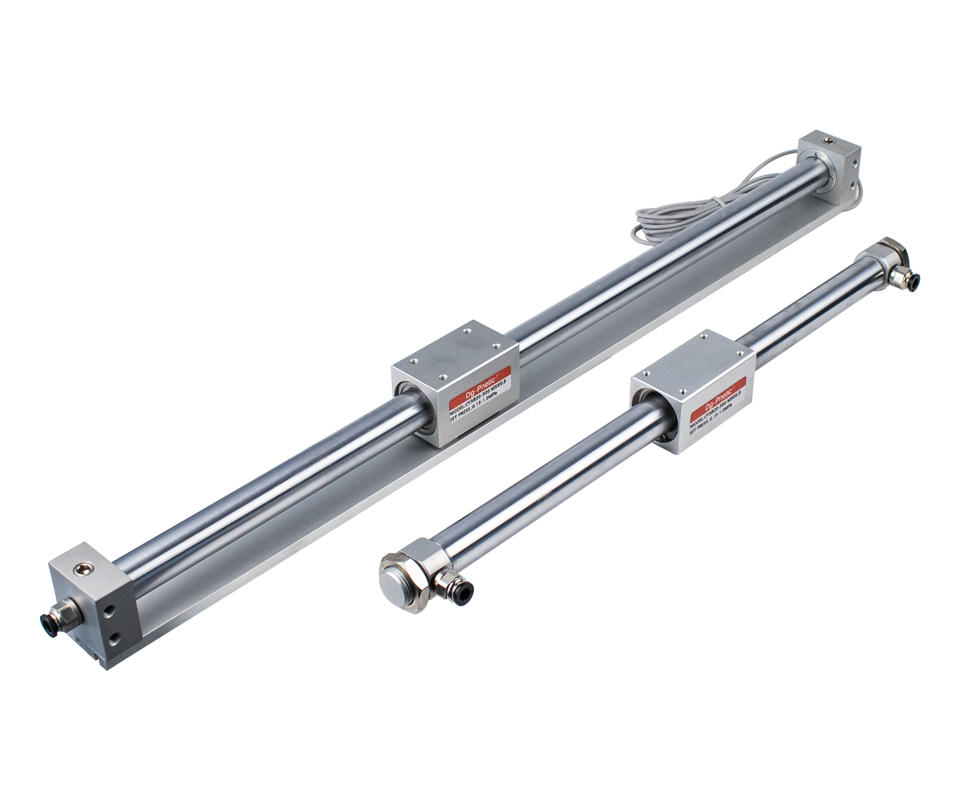
Bore Size(mm): 6, 10, 15, 20, 25, 32, 40, 50, 63
Action: Double Acting
Working Pressure:
0.16~0.70Mpa (22Psi~100Psi) (1.6~7Bar)
Working Temperature ℃: -10~60℃. (No Freezing)
Cushion Type: Rubber Buffer or Hydraulic Buffer
Stroke Tolerance:
Stroke 0-250: 0-1.0mm; 251-1000: 0-1.4mm; 1001-… : 0-1.8mm.
Piston Speed: 50~500mm/s
Standard Stroke(mm): 50 100 150 … 1000mm
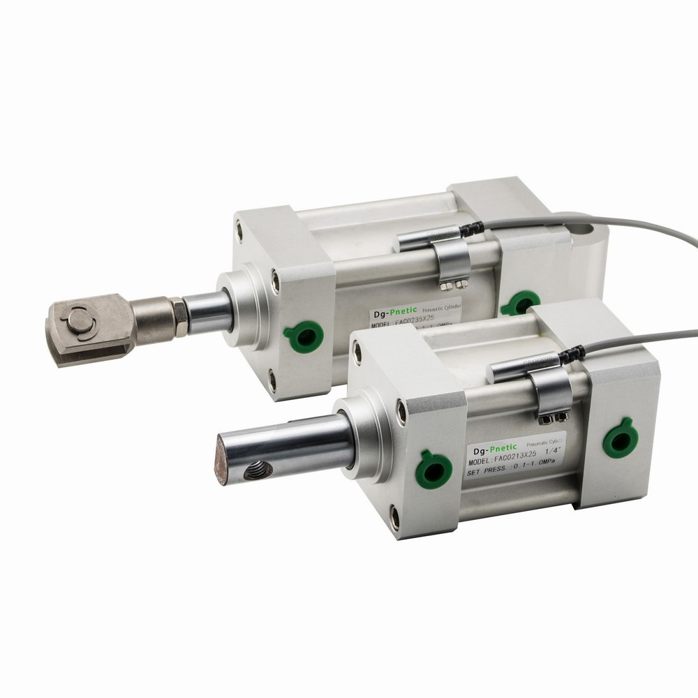
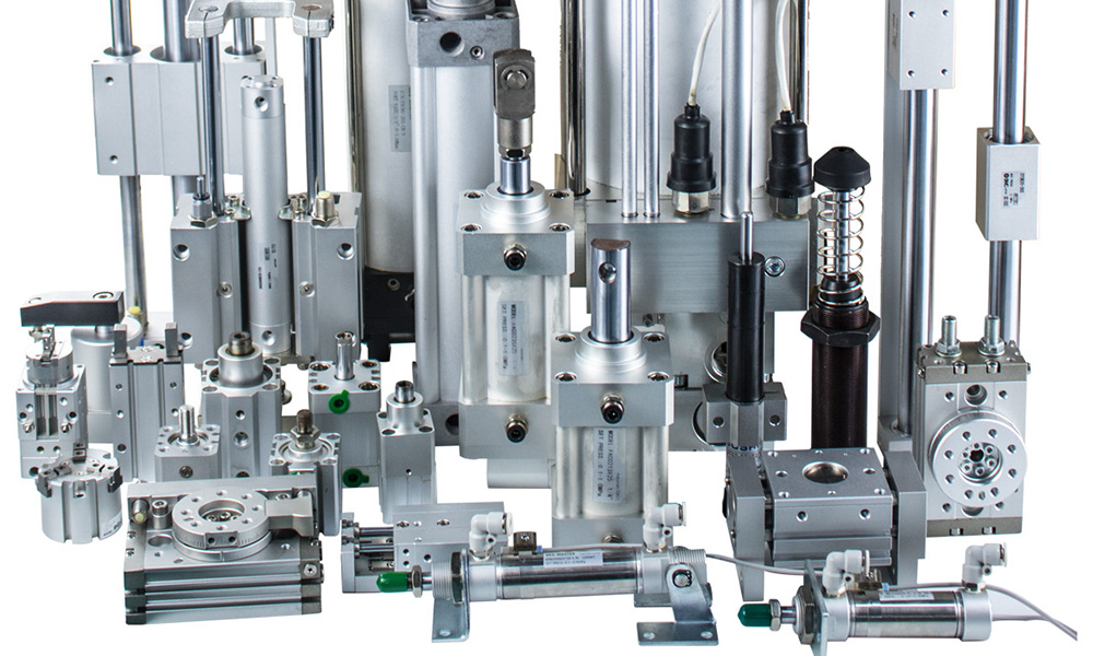
Pneumatic linear actuators—also known as air cylinders or pneumatic cylinders—are devices designed to move objects in a straight line using compressed air. They offer one of the simplest, most cost-effective, and reliable solutions for achieving linear motion in automated systems.
 Applications Across Industries
Pneumatic actuators are widely used across industrial automation, including:
Factory machinery
Packaging systems
Material handling
Transportation lines
Life sciences and cleanroom environments
Their versatility and efficiency make them a go-to choice for linear movement in countless applications.
 Construction & Materials
Most pneumatic actuators are made of aluminum, valued for its light weight and corrosion resistance—such as Parker’s P1F-S series, which is suitable for a wide range of applications.
For harsh or hygienic environments (e.g., food processing, washdown zones), stainless steel models are preferred. These prevent corrosion and reduce contamination risks. Some models may also include:
Wiper seals and metallic scrapers to remove external debris
Powder coating or anodizing to resist aggressive cleaning agents
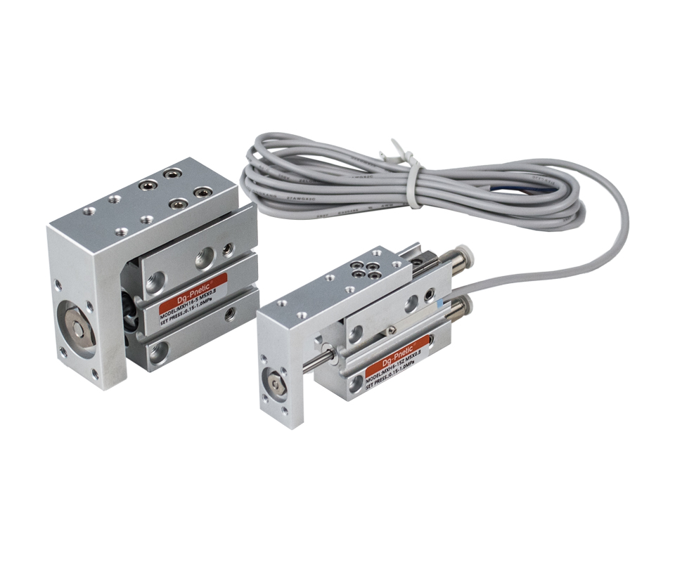
Bore Size(mm): 6, 10, 16, 20
Working Pressure:
Min. Pressure: 0.15 Mpa (22 Psi) (1.5 Bar)
Max. Pressure: 0.7 Mpa (100 Psi) (7 Bar)
Proof Pressure: 1.50Mpa(213Psi)(15.0Bar)
Working Temperature ℃: -10~60℃. (No Freezing)
Cushion Type: Bumper on both end.
Piston Speed: 50~500mm/s
Standard Stroke(mm): 5 10 20 25 30 40 50 60
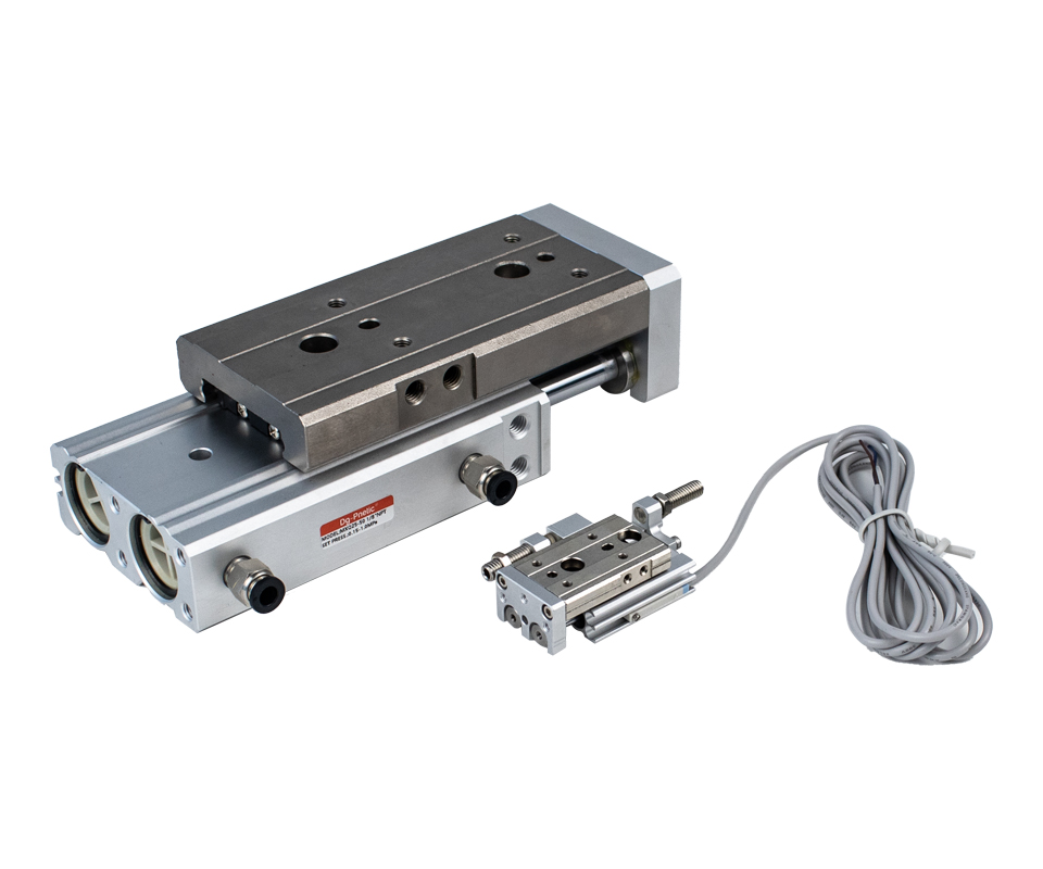
Bore Size(mm): 6, 10, 16, 20, 25
Working Pressure:
Min. Pressure: 0.15 Mpa (22 Psi) (1.5 Bar)
Max. Pressure: 0.7 Mpa (100 Psi) (7 Bar)
Proof Pressure: 1.50Mpa(213Psi)(15.0Bar)
Working Temperature ℃: -10~60℃. (No Freezing)
Cushion Type: Bumper or hydraulic buffer
Piston Speed: 50~500mm/s
Standard Stroke(mm): 10 20 25 30 40 50 75 100, 125, 150.
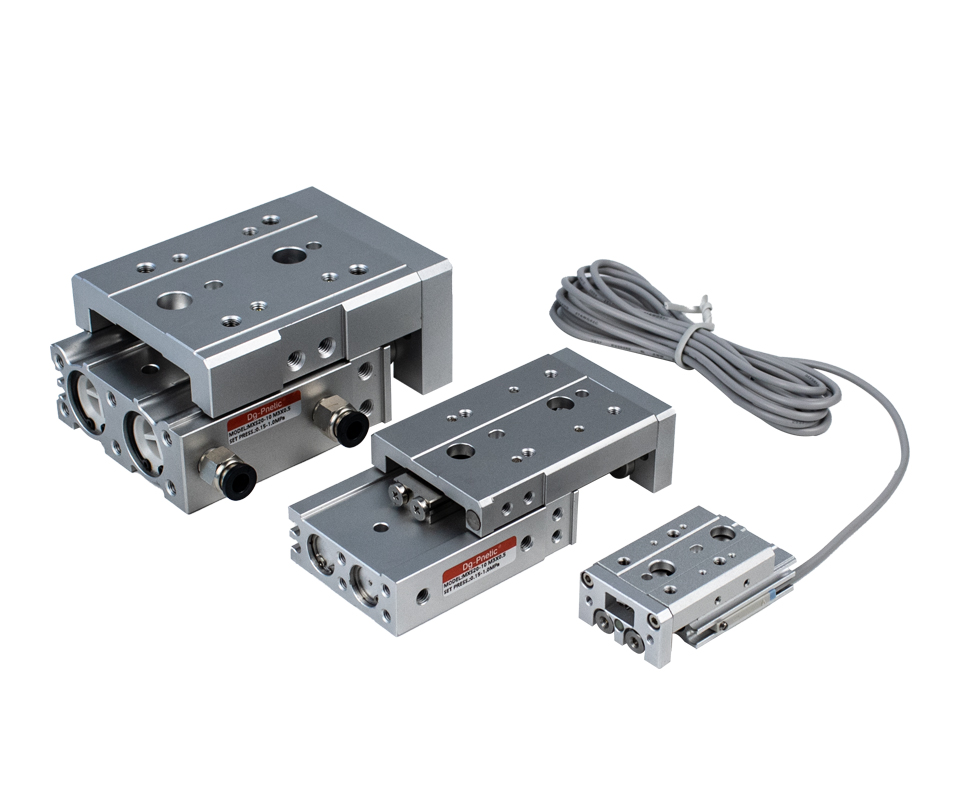
Bore Size(mm): 6, 10, 16, 20, 25
Working Pressure:
Min. Pressure: 0.15 Mpa (22 Psi) (1.5 Bar)
Max. Pressure: 0.7 Mpa (100 Psi) (7 Bar)
Proof Pressure: 1.50Mpa(213Psi)(15.0Bar)
Working Temperature ℃: -10~60℃. (No Freezing)
Cushion Type: Bumper
Piston Speed: 50~500mm/s
Standard Stroke(mm): 10 20 25 30 40 50 75 100, 125, 150.
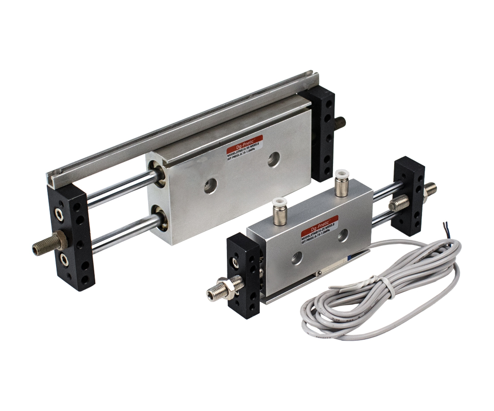
Bore Size(mm): 6, 10, 16, 20, 25
Working Pressure:
Min. Pressure: 0.10 Mpa (14 Psi) (1.0 Bar)
Max. Pressure: 0.7 Mpa (100 Psi) (7 Bar)
Proof Pressure: 1.50Mpa(213Psi)(15.0Bar)
Working Temperature ℃: -10~60℃. (No Freezing)
Cushion Type: Bumper or hydraulic buffer
Piston Speed: 30~500mm/s
Standard Stroke(mm): 10 20 25 30 40 50 75 100, 125, 150, 175, 200, 250
 A guided cylinder
Consists of a guide rod or slider running parallel to the piston rod and the cylinder body. Another design uses two parallel pistons and piston rods. In the double-piston rod cylinder, the ends of both piston rods are connected by a flange, which prevents the piston from rotating and simultaneously provides double the output force.
This type of cylinder features a compact structure, high guiding accuracy, and can withstand significant lateral loads and moments of force. It is commonly used to withdraw, lift, and position workpieces on conveyor lines.
Guide Rod TypesThere are typically two types of rail bearings for the guide rod:
Sliding Bearing: Offers excellent abrasion resistance and can bear lateral loads more than twice that of stopper cylinders, making it ideal for stopper applications.
Ball Bearing: Enables high-precision, smooth movement and has a long service life, perfect for moving and lifting workpieces on conveyor belts.
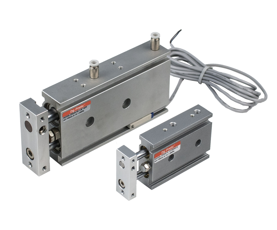
Bore Size(mm): 20, 25, 32
Working Pressure:
Min. Pressure: 0.10 Mpa (14 Psi) (1.0 Bar)
Max. Pressure: 0.7 Mpa (100 Psi) (7 Bar)
Proof Pressure: 1.05Mpa(213Psi)(15.0Bar)
Working Temperature ℃: -10~60℃. (No Freezing)
Cushion Type: Air Cushion
Piston Speed: 50~1000mm/s
Standard Stroke(mm): 20 25 30 35 40 45 50 60 70 75 80 90 100
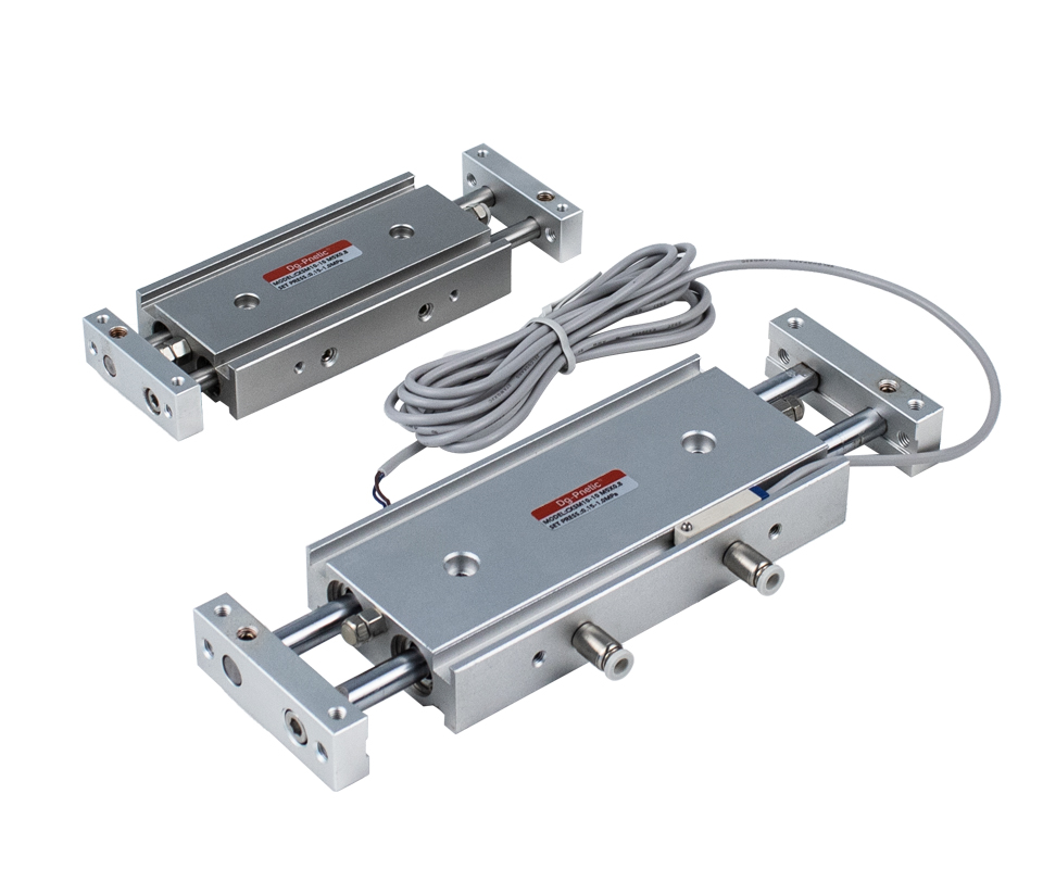
Bore Size(mm): 6, 10, 15, 20, 25, 32
Working Pressure:
Min. Pressure: 0.15 Mpa (22Psi) (1.5 Bar)
Max. Pressure: 0.7 Mpa (100 Psi) (7 Bar)
Proof Pressure: 1.05Mpa(213Psi)(15.0Bar)
Working Temperature ℃: -10~60℃. (No Freezing)
Cushion Type: Bumper
Piston Speed: 50~500mm/s
Standard Stroke(mm): 20 25 30 35 40 45 50 60 70 75 80 90 100 125 150 175 200
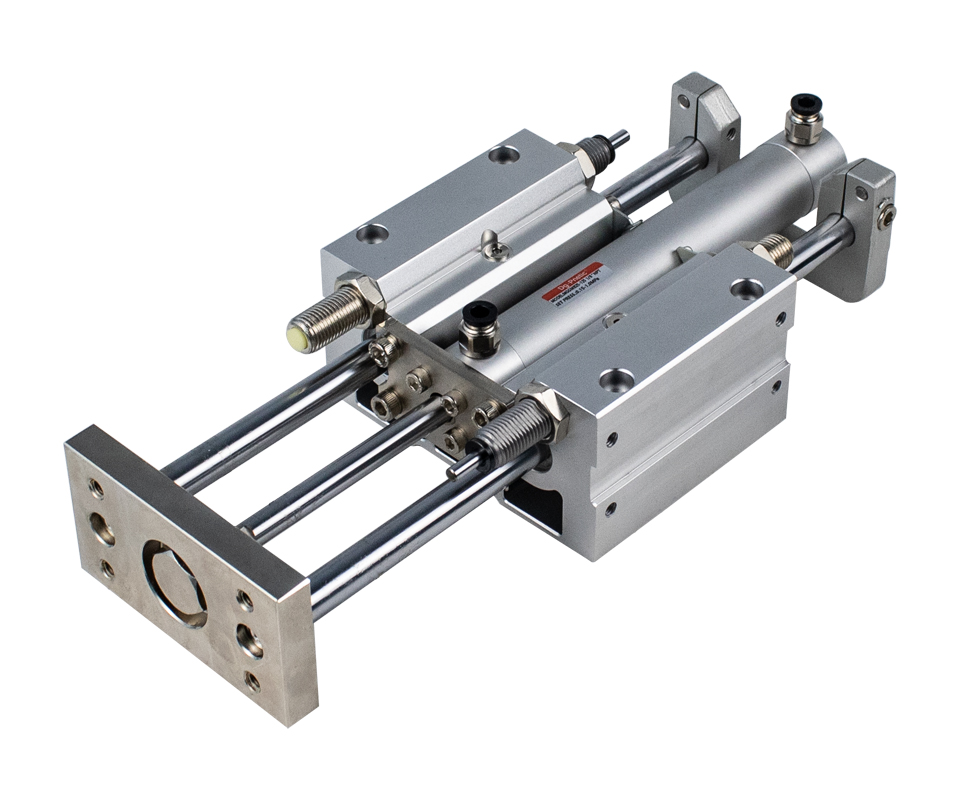
Bore Size(mm): 20 25 32 40 50 63 80 100
Working Pressure:
Min. Pressure: 0.15 Mpa (22Psi) (1.5 Bar)
Max. Pressure: 1.0 Mpa (140 Psi) (10 Bar)
Proof Pressure: 1.05Mpa(213Psi)(15.0Bar)
Working Temperature ℃: -10~60℃. (No Freezing)
Cushion Type: Built-in shock absorber
Piston Speed: 50~700mm/s
Standard Stroke(mm): 75 80 90 100 125 150 175 200~300
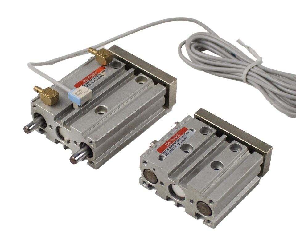
Bore Size(mm): 20 25 32 40 50 63 80 100
Working Pressure:
Min. Pressure: 0.1 Mpa (14Psi) (1.0 Bar)
Max. Pressure: 1.0 Mpa (140 Psi) (10 Bar)
Proof Pressure: 1.05Mpa(213Psi)(15.0Bar)
Working Temperature ℃: -10~60℃. (No Freezing)
Cushion Type: Rubber bumper
Piston Speed: 50~400mm/s
Standard Stroke(mm): 10~75 80 90 100 125 150 175 200~400
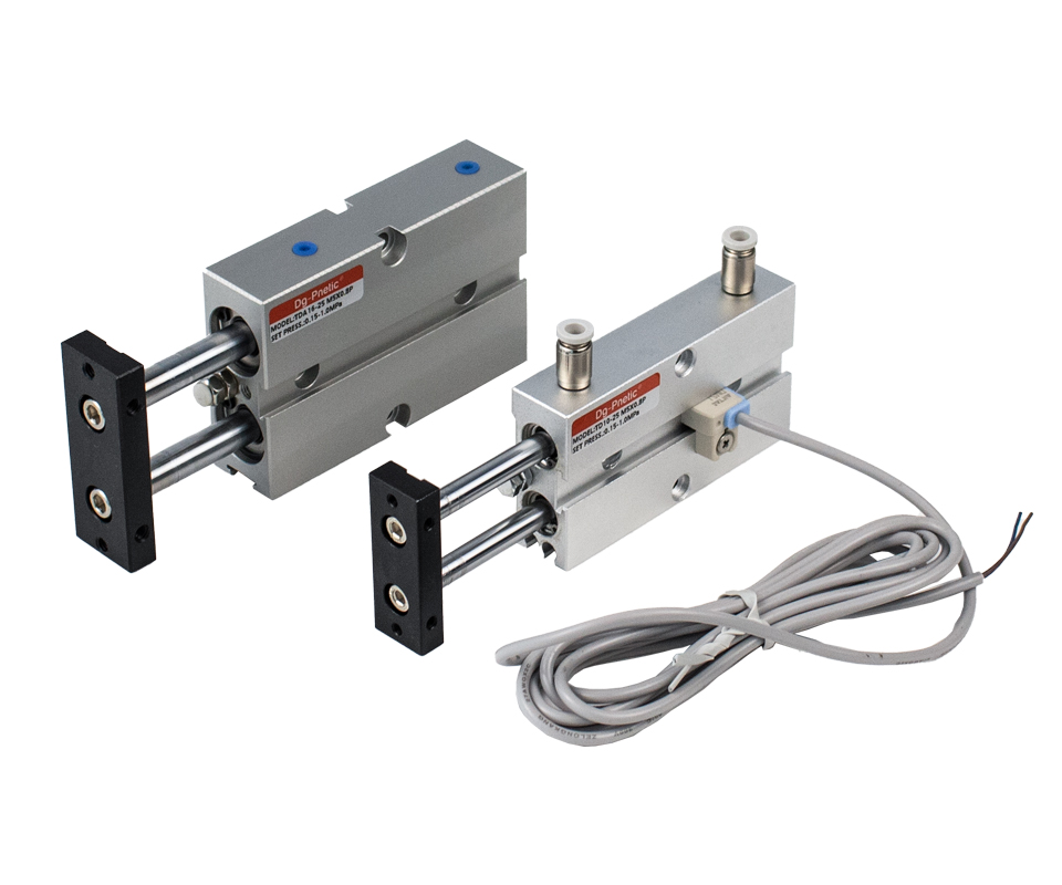
Bore Size(mm): 6 10 16 20 25 32 40
Working Pressure:
Min. Pressure: 0.1 Mpa (14Psi) (1.0 Bar)
Max. Pressure: 0.85 Mpa (120 Psi) (8.5 Bar)
Proof Pressure: 1.05Mpa(213Psi)(15.0Bar)
Working Temperature ℃: -10~60℃. (No Freezing)
Cushion Type: Rubber bumper
Piston Speed: 50~700mm/s
Standard Stroke(mm): 10~75 80 90 100 125 150 175 200~400
 Installation & Operation Guidelines for Guided Cylinders
 Filter the Air Supply
Ensure that the compressed air is filtered through a 40 µm filter before entering the cylinder to prevent contamination and damage to internal components.
 Install on a Flat Surface
The cylinder body must be mounted on a flat, level surface. Any bending or twisting of the guide rod can significantly increase movement resistance, accelerate bearing wear, and reduce overall performance.
 Avoid Surface Damage
The sliding surfaces of the piston rod and guide rod should be kept free of scratches or damage. Damaged surfaces can compromise seal integrity and eventually cause air leakage.
 Prevent Sudden Movements
Be aware that sudden or unintended cylinder motion can occur due to mechanical distortion, jamming of sliding parts, or unexpected changes in applied forces. Take precautions during installation and use.
 Consider Damping Solutions
Depending on the application, it may be necessary to include a speed-reduction circuit or install a shock absorber to ensure smooth and safe operation.
 Key Selection Criteria for Rodless Cylinders
 Stroke Speed
This refers to the piston’s movement speed within the cylinder. It depends on the air pressure at each port and the load weight. Ensure the system is designed to provide consistent and appropriate airflow to maintain the desired speed.
Carrier Load Capacity
The carrier must support and move the mounted load safely and effectively. Proper alignment between the rod axis, load, and direction of movement is critical to prevent binding and wear.
 Dead Length
Consider the dead length—the minimum required space for installation and maintenance access. Ensure there is enough room at both ends for safe mounting and servicing.
 Stroke Length
Always operate the cylinder within its maximum usable stroke range. Exceeding this can cause piston or sealing damage, leading to performance issues or failure.
 Air Pressure Supply
Rodless cylinders are powered by compressed air, so a reliable and consistent pressure source is essential. Use filtered air to prevent internal contamination and extend service life.
 Bore Size
Select the bore diameter based on the force output required. Larger bore sizes deliver higher force and are recommended for heavy-duty applications where maximum capacity is needed.