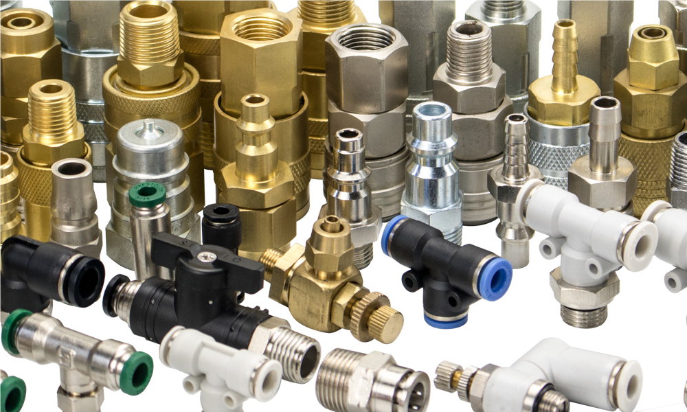
 What Is a Hydraulic Shock Absorber?
A hydraulic shock absorber is a device that converts kinetic energy into heat energy via hydraulic resistance. Inside, fluid is forced through precision-engineered orifices and valves, creating resistance that slows down the moving mass smoothly and predictably.
Uniform deceleration with low peak force
Minimal shock to the load and machine structure
Precise energy dissipation with reliable stroke control
Can stop or slow objects with very little bounce-back
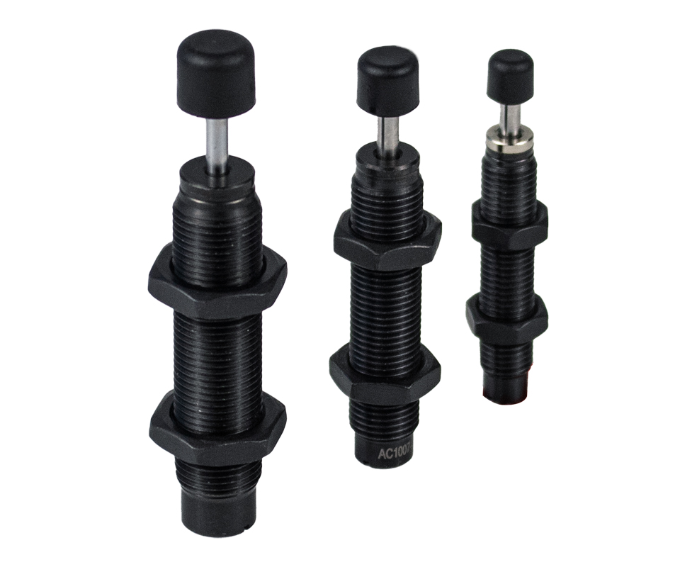
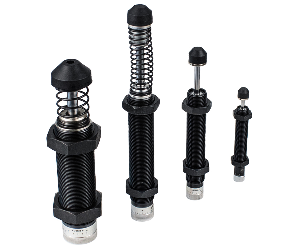
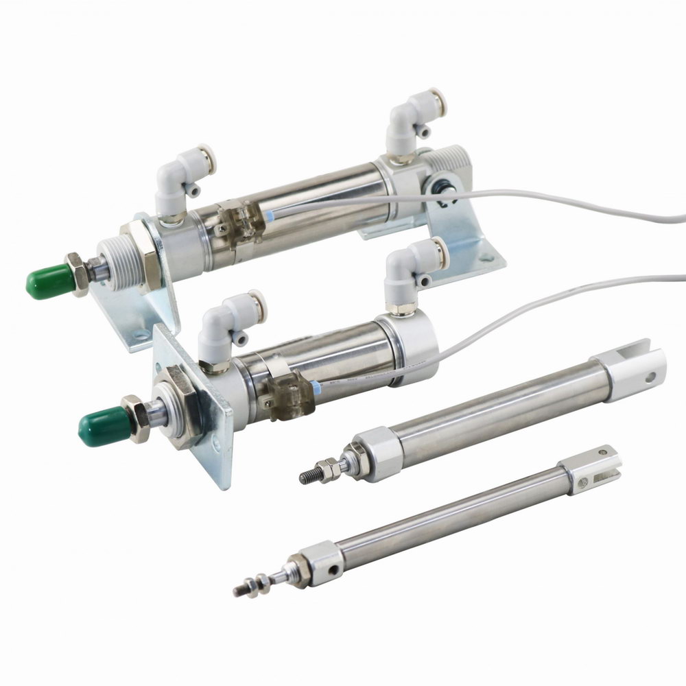
AC Bore Szie(mm): 06 08 10 12 14 20 25 36.
1. Small size and compact structure make it suitable for narrow spaces
2. It cannot be disassembled due to its high safety properties.
3. The outer pressure cylinder has a full thread for flexible installation and adjustment.
4. The load should not be directly applied to the end cap. Otherwise, a deformed end face will seriously affect the stroke reset.
AD bore size (mm): 14 20 25 36 42 64
1. 0-270° one-side eccentric adjustment effectively expands the adjustment range.
2. One-hole damping structure (-5 series) and multi-hole buffering structure are available for your selection based on your specific requirements.
3. The full thread of the outer pressure cylinder is flexible for installation and adjustment.
4. The combination of a special purpose sealing device and special hydraulic oil. enhances the buffering properties and service life.
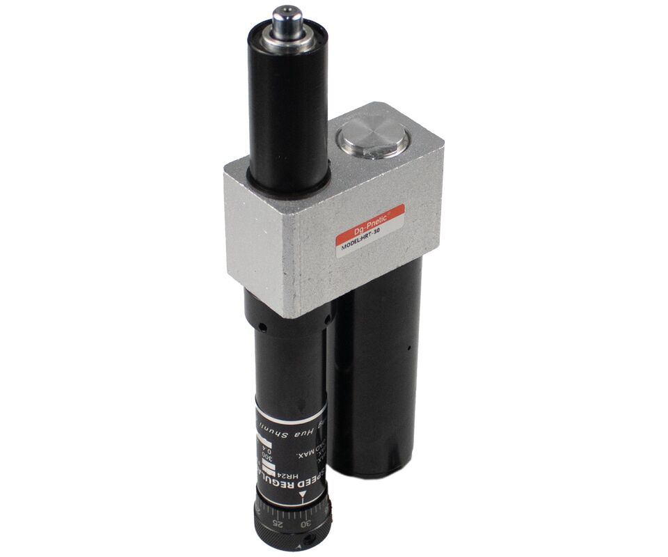
 Adjustable Hydraulic Speed Stabilizers (Hydraulic Dampers)
A hydraulic speed stabilizer is a specialized version of a hydraulic shock absorber. It not only absorbs impact but also maintains a stable moving speed for the load after the initial collision, making it ideal for applications requiring controlled motion over a stroke.
Similar internal structure to standard absorbers
Unlike traditional models, which gradually close off flow channels as the piston moves forward (causing increasing resistance),
Speed stabilizers maintain a constant number of flow outlets over a set distance,
This provides steady velocity, followed by smooth deceleration at the end of the stroke
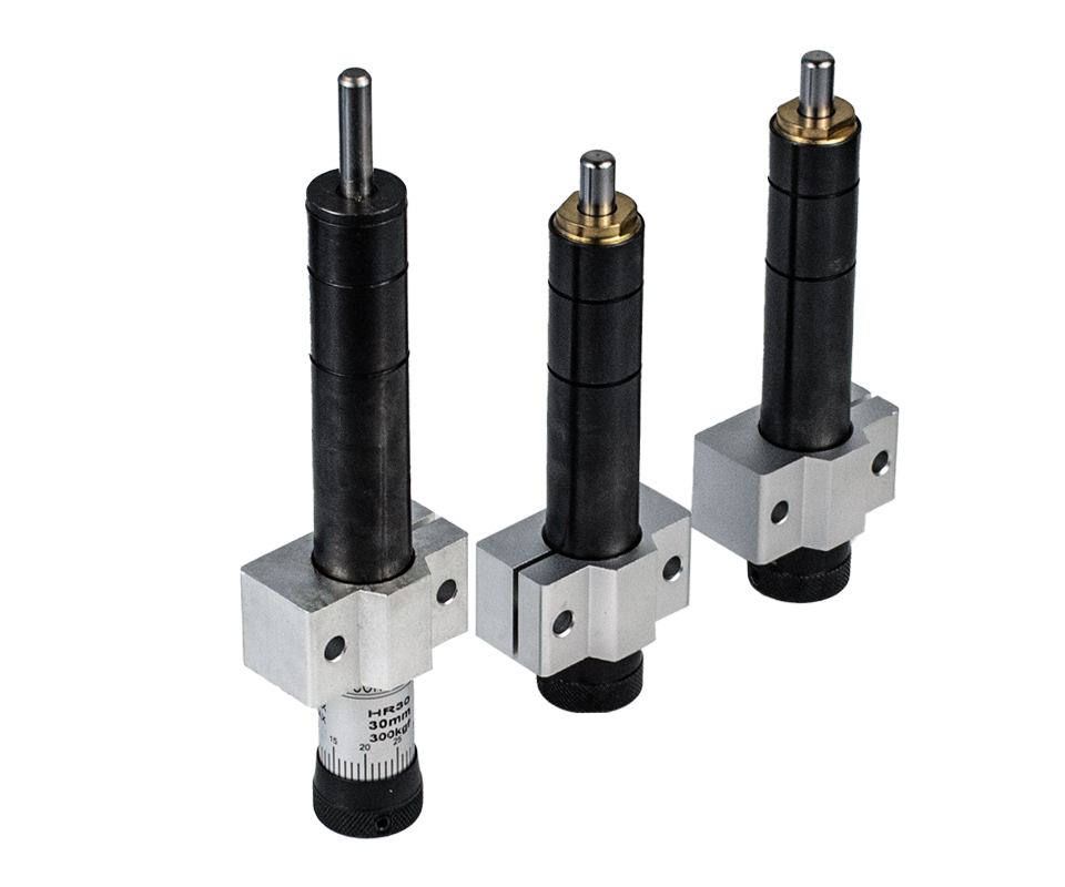
Bore size(mm): 15 30 60 80 100.
1. Adopted whole closed structure which no needs the supplement of hydraulic oil, it can keep long period of stable function.
2. The suddenly fluctuation of load will not influence the buffer speed too much, so we could get the stable run speed.
3. Feed speed can be adjusted simply by the adjustable knob.
4. Keeping a long and stable control and making regress diaplasis with spring.
5. Because the viscosity of oil is very stable along with the temperature change, so the function of steady speed is very good.
6. When the load of axes in HR shock absorbers uninstall, the spring will self-fighing.
Features
Stroke(mm): 60 100
1. Even though get rid of the load of the HRT damper, the piston rod will stop atprimary position, and the piston rod must be reverted by compressed air.
2. The piston rod can stop at any position, so it is easy for subsection feed control.
 The Buffering Effect Compared With Other Device
 How Moving Loads Are Stopped: Energy Absorption Methods
All moving objects possess kinetic energy, which is determined by their mass and velocity. To safely bring a moving object to a stop, this energy must be absorbed or dissipated. Common energy-absorbing devices include rubber bumpers, compression springs, and dashpots, all of which achieve deceleration by compressing or resisting motion—though not always efficiently.
Rubber Bumpers, Springs, and DashpotsRubber bumpers and springs absorb energy by deforming and then rebounding.
A dashpot consists of a piston moving through a fluid-filled cylinder, with the fluid escaping through a restricted orifice. This setup produces:
High resistance at the start of the stroke
Reduced resistance as the piston retracts
While these devices can stop motion, they do not dissipate energy uniformly. The result is typically a sharp peak force during impact, which can transmit shock loads to the machinery or structure.
 Why Use a Shock Absorber?
To dissipate energy more smoothly and consistently, a shock absorber is used. Unlike springs or bumpers, shock absorbers provide a controlled deceleration, spreading the impact force more evenly throughout the stroke.
This minimizes peak forces
Reduces wear on equipment
Improves system stability and lifespan
 Comparing Force vs Stroke
A force-vs-stroke diagram for the same load and velocity shows:
| Device | Energy Dissipation Pattern |
|---|---|
| Rubber Bumper | Sharp peak → rapid drop (hard impact) |
| Spring | Linear buildup → strong rebound |
| Dashpot | High resistance at first → tapering off |
| Shock Absorber | Nearly square curve (ideal) → constant deceleration |
 The Ideal Deceleration Curve
A linear deceleration profile—represented by an almost square force-stroke curve—is the most efficient way to stop a moving object. It delivers the optimal balance of:
Controlled force
Minimal stopping distance
Short deceleration time
 Shock absorbers are the best solution when consistent, safe, and equipment-friendly stopping is required.