products


tech info
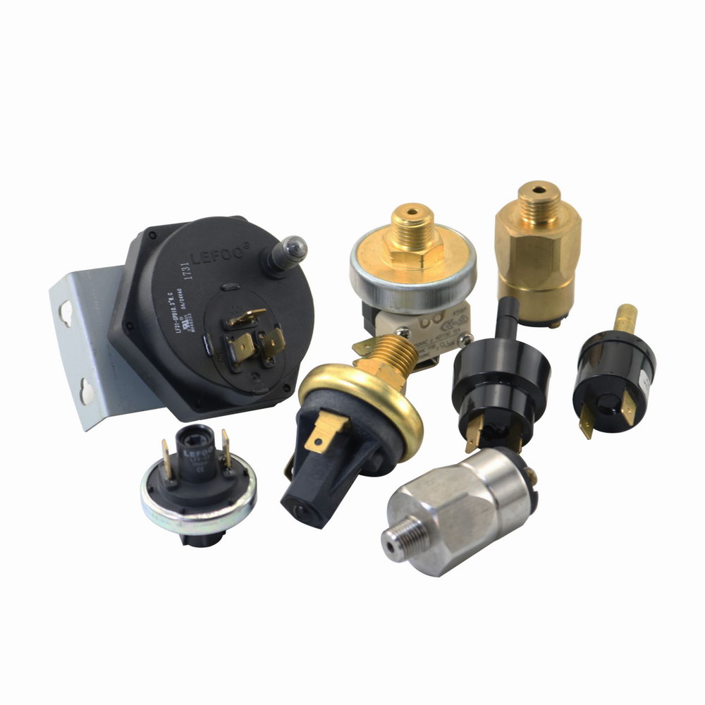
Electric Water Vcalve
Steam Solenoid Valve
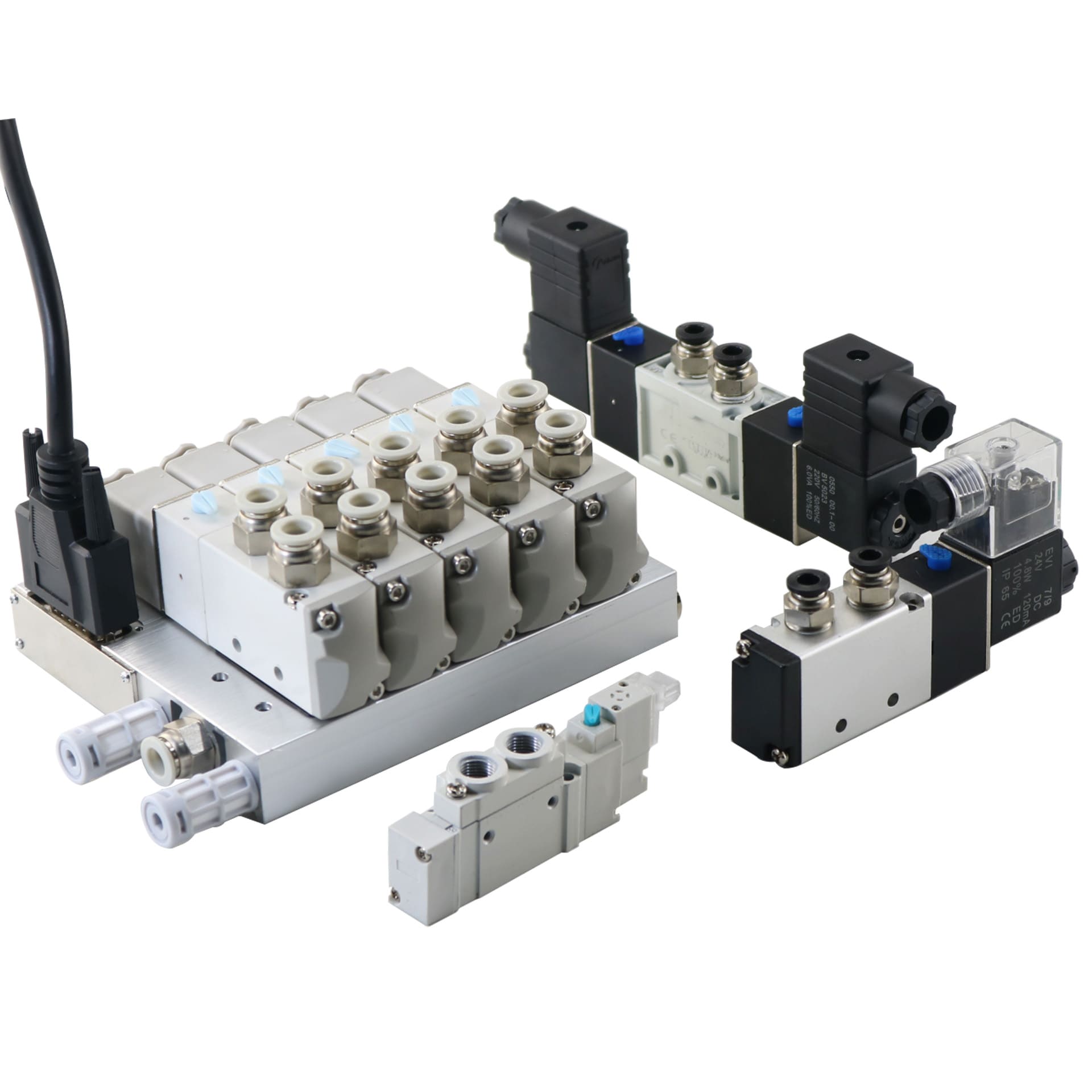
What's The Air Solenoid Valvce?
Two Ways Solenoid Valve Normal Purpose
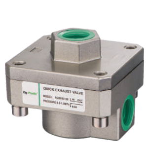
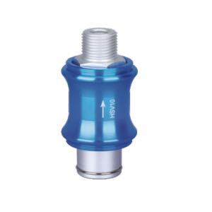
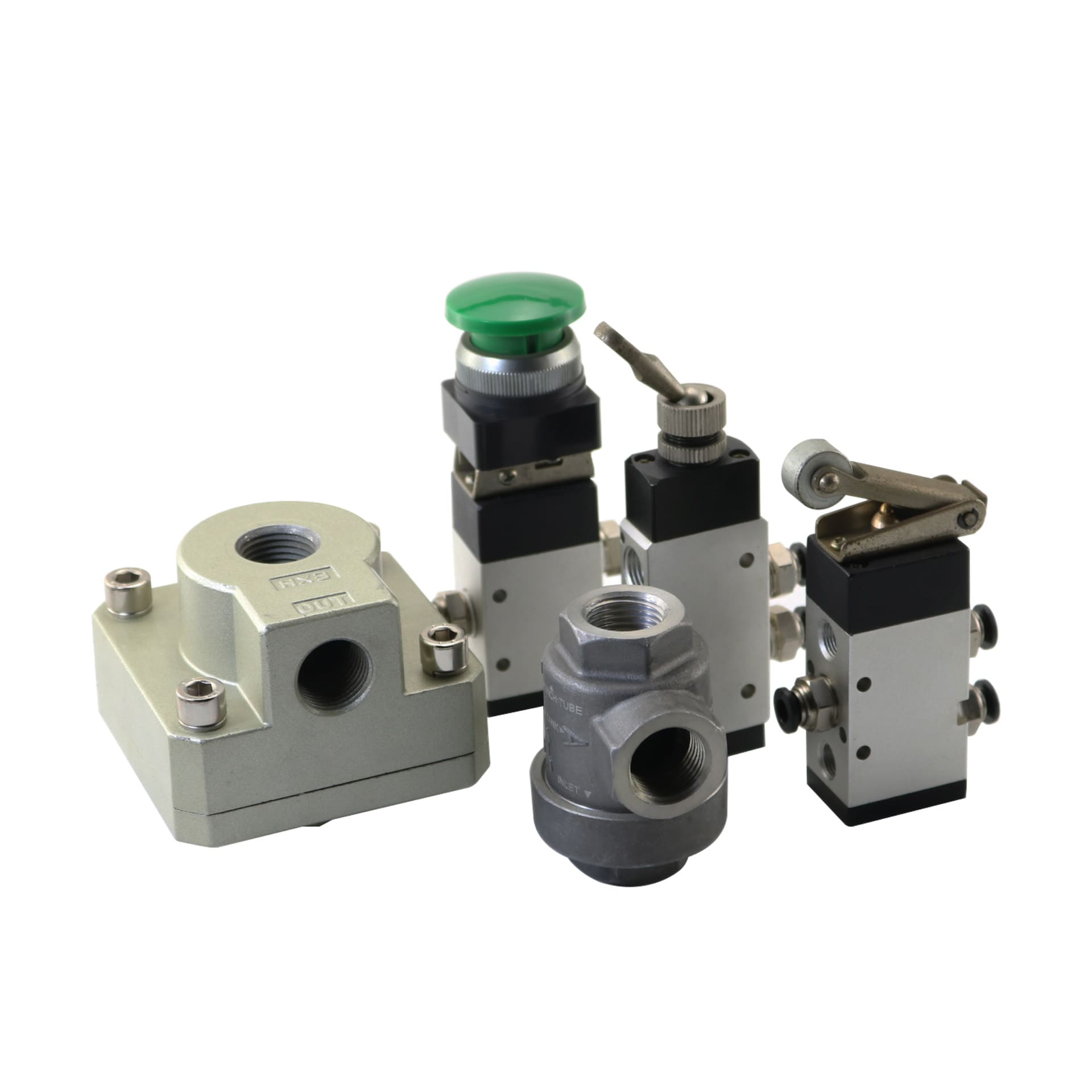
Auto Drain Valve
All Product Information
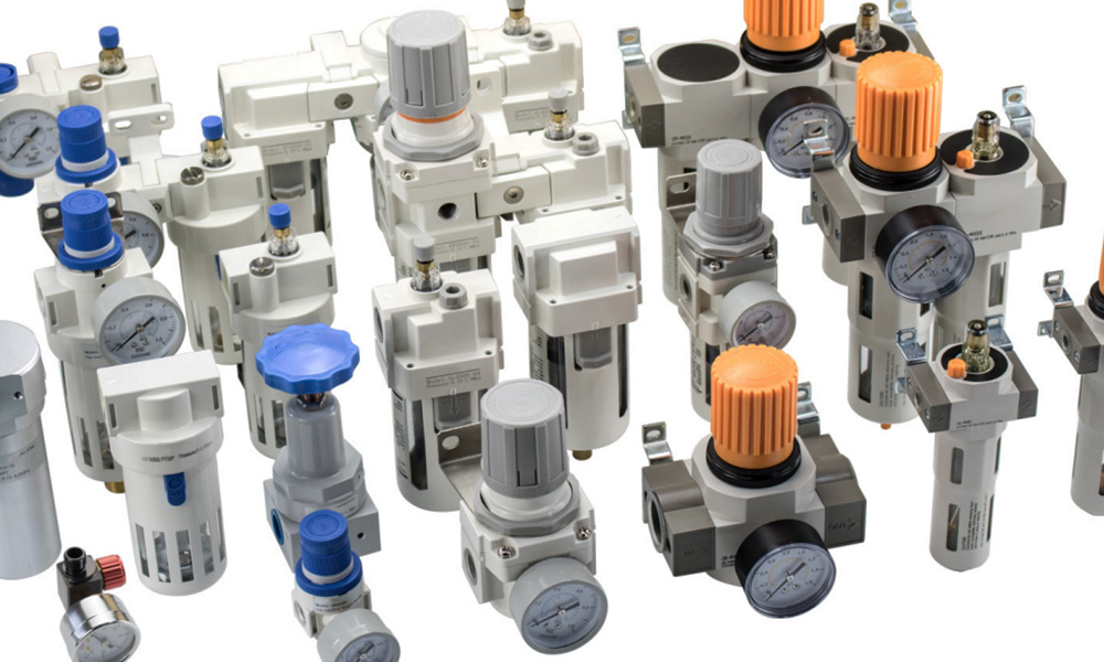
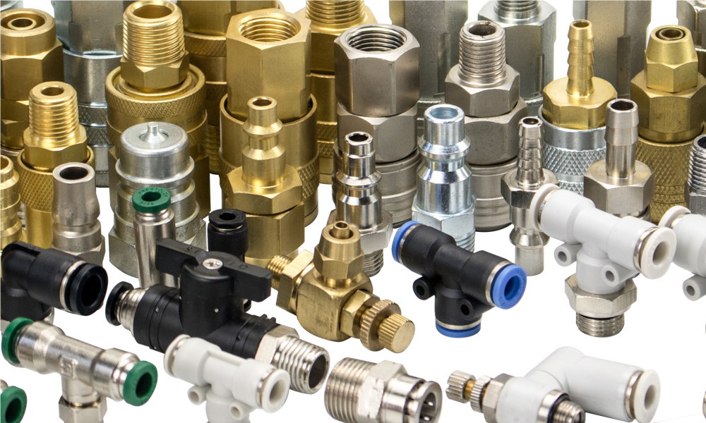
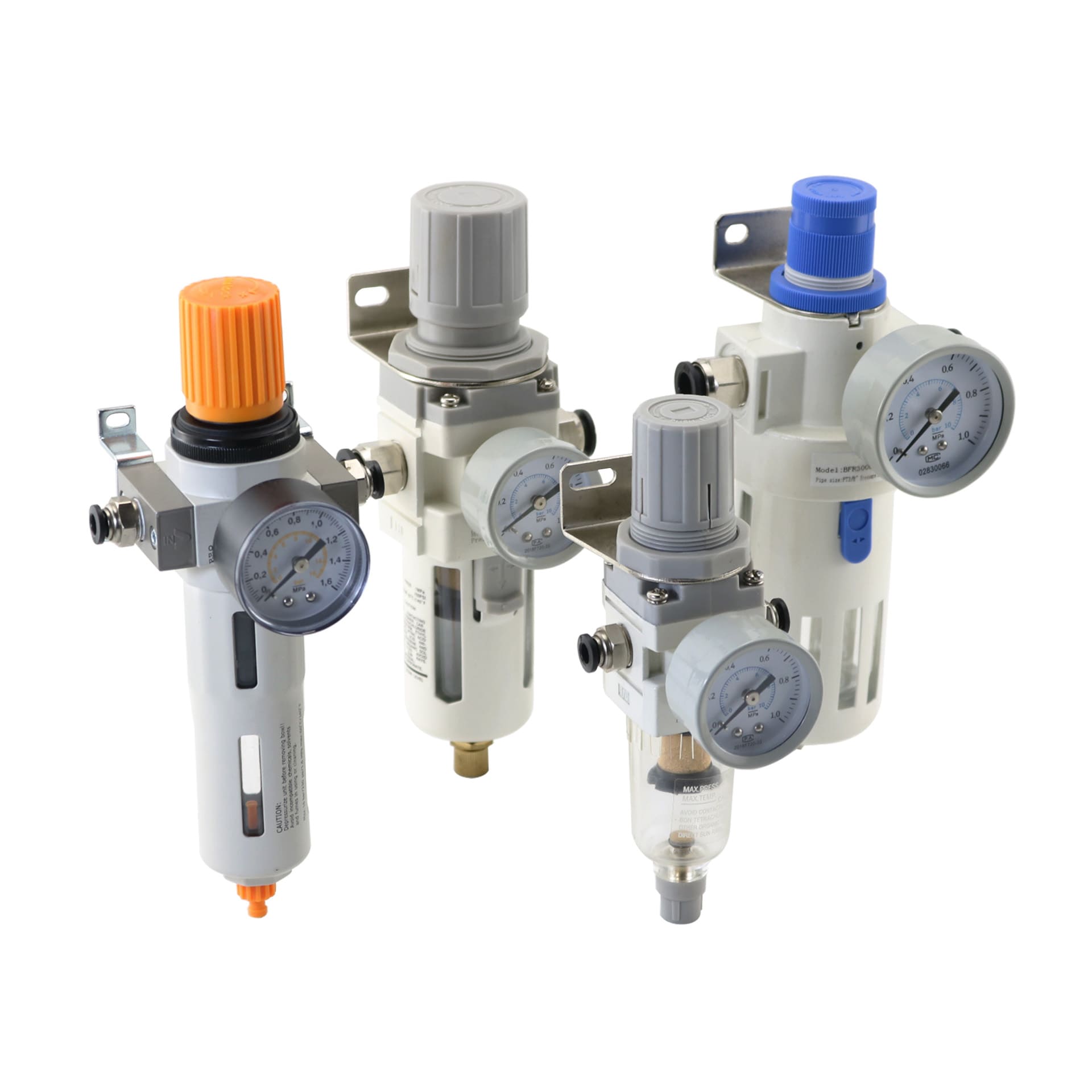
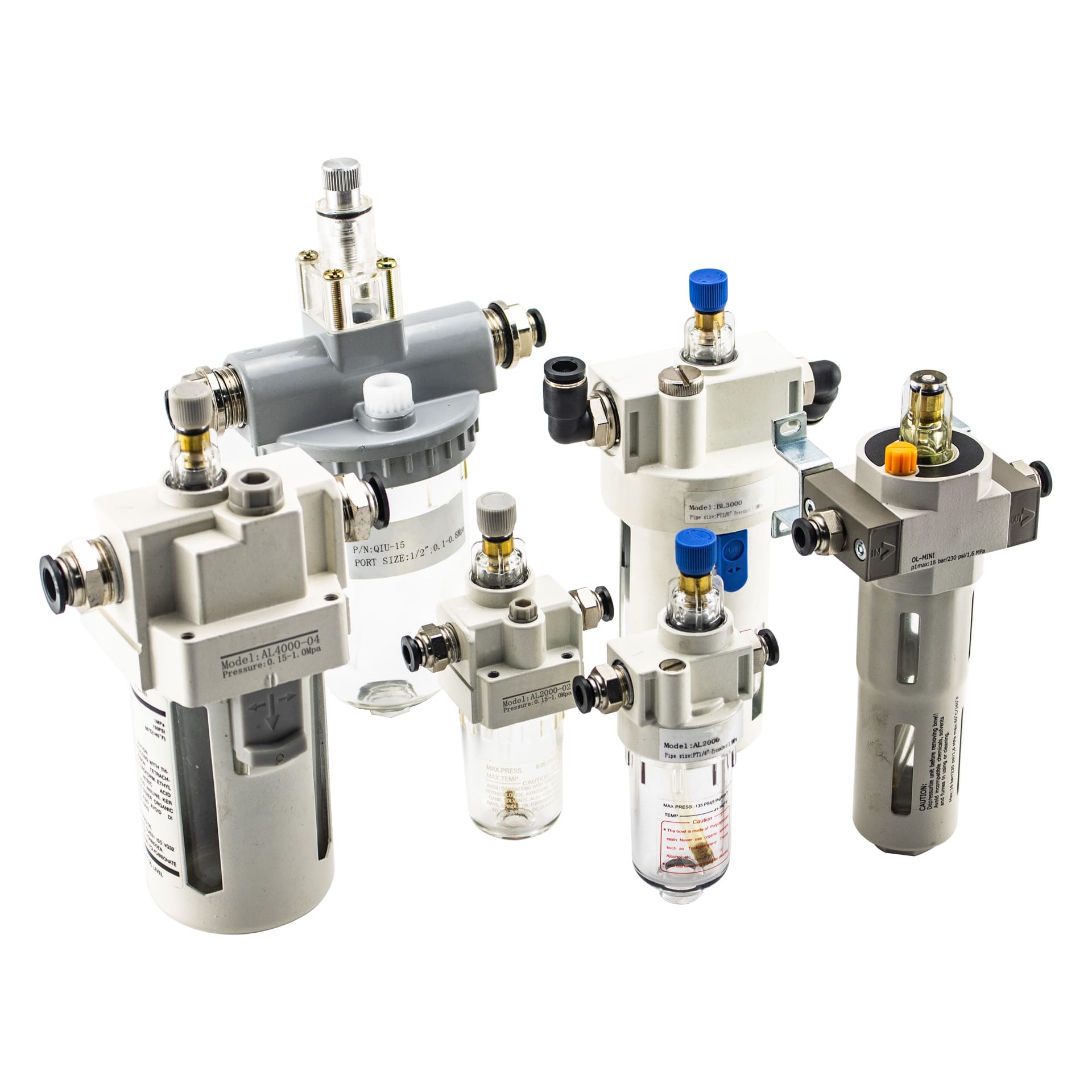
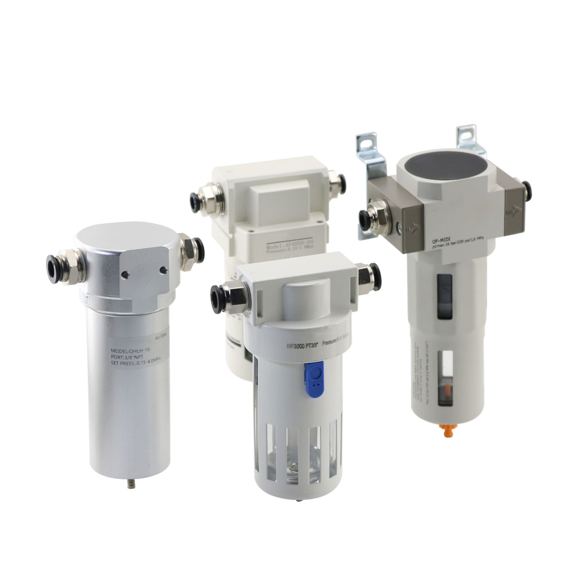
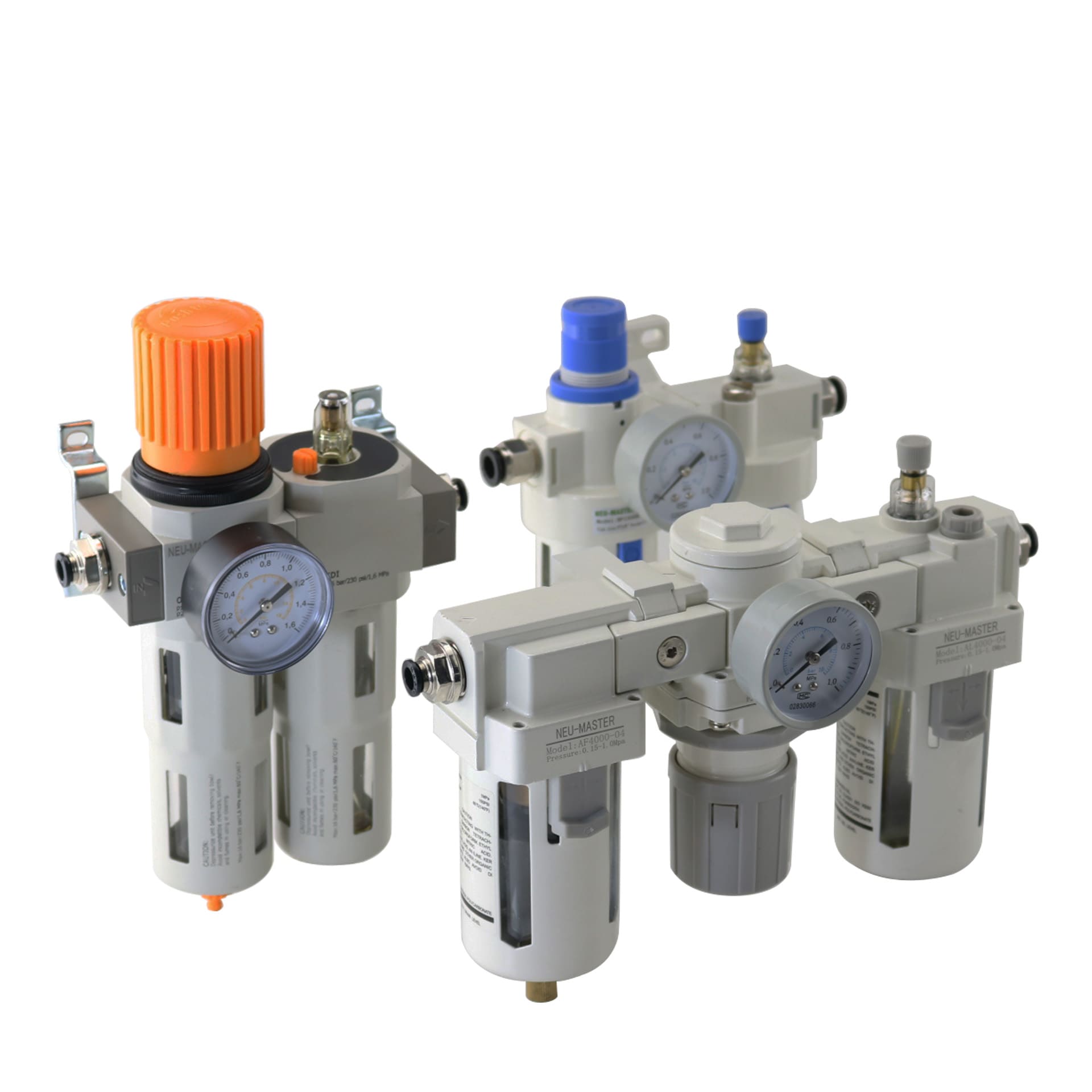
Air Filter Regulator Lubricatorc
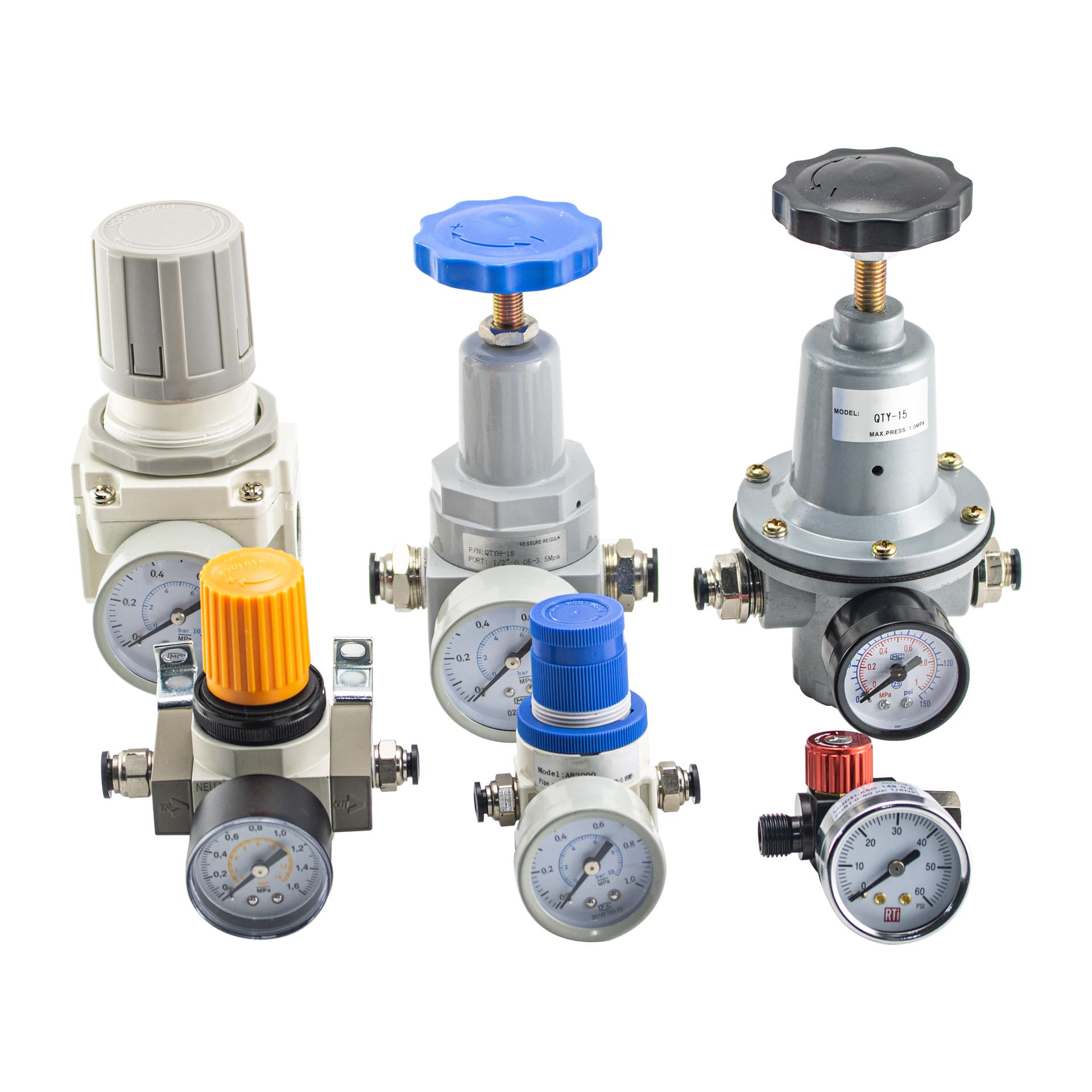
Air Compressor Filter Regulator
Air line lubricatorc
Air Compressor Filter Regulator
FRL Unit
All Product Information
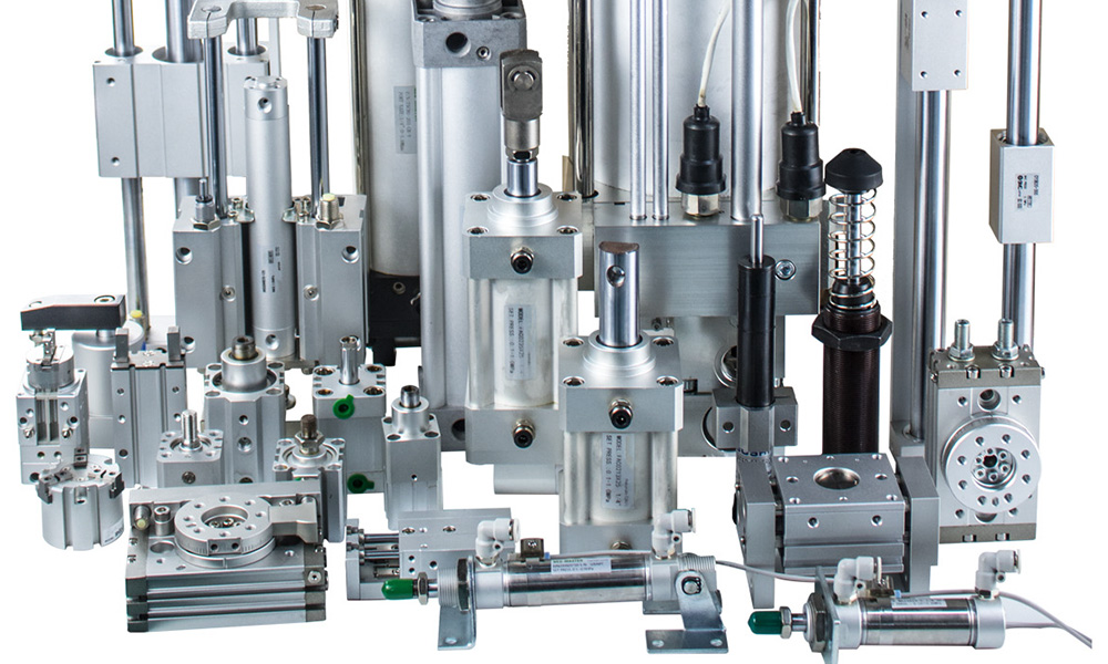
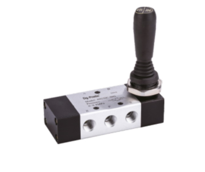
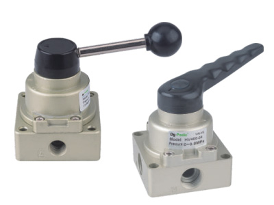
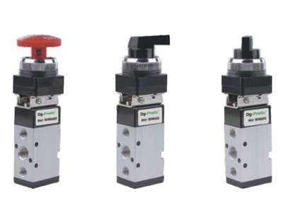
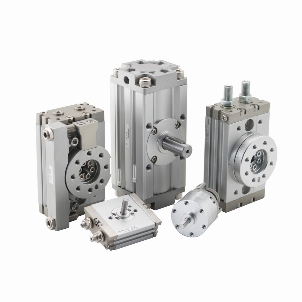
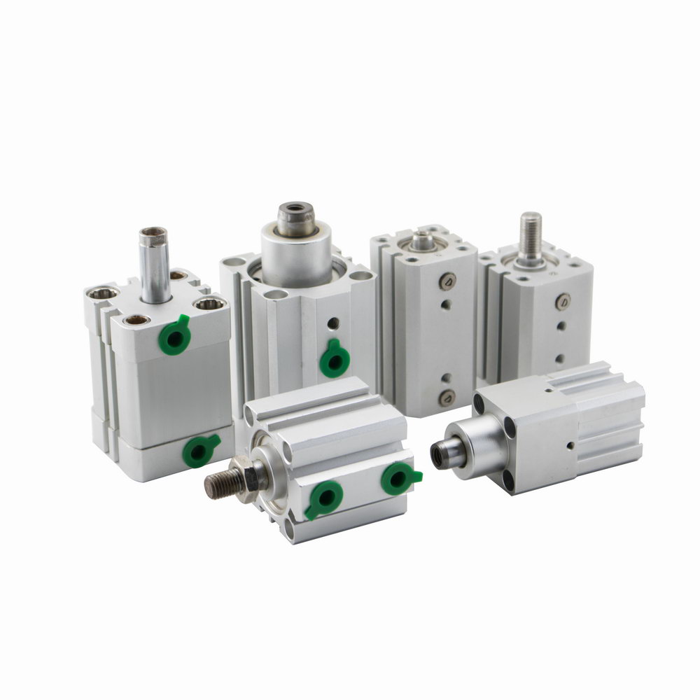
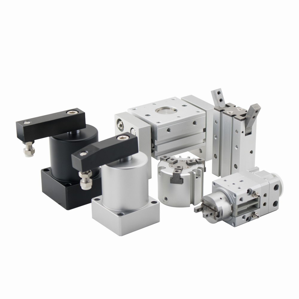
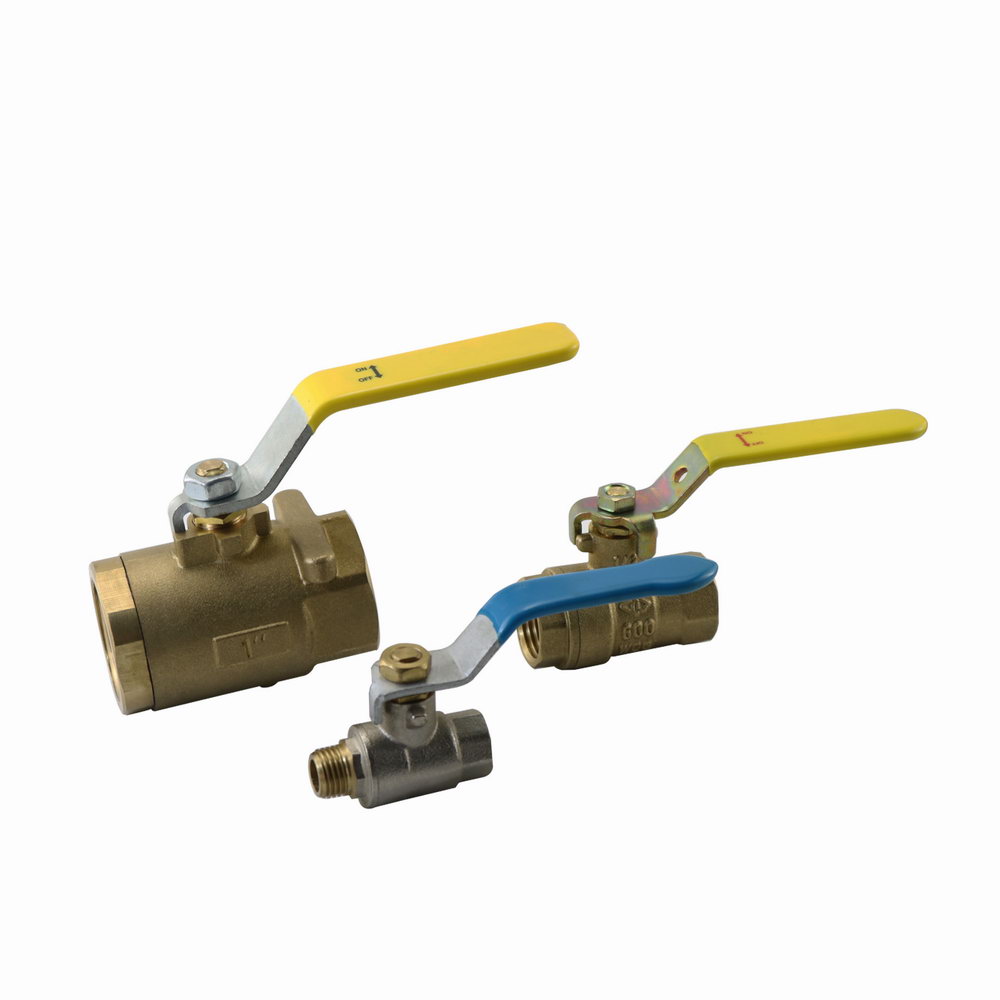
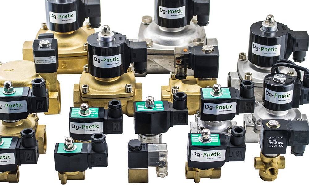
Pneumatic Valves
Air Filter Regulator Lubricator