
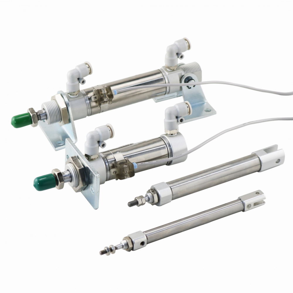
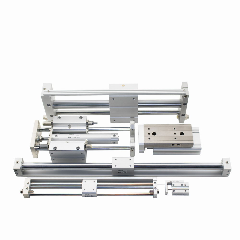
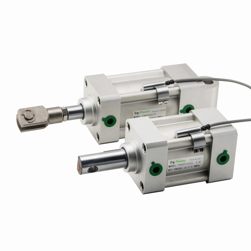
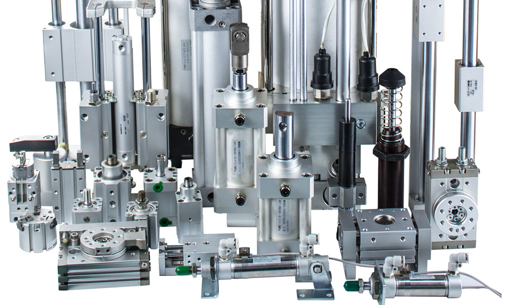
They share the same internal structure as standard pneumatic cylinders and are available in both double-acting and single-acting types.
 Size falls between profile cylinders (larger) and sub‑miniature/micro cylinders (smaller), typically featuring a round barrel.
Best suited for light-duty, low-force applications. Micro-air cylinders within this category excel at small part positioning, clamping, and ejecting.
They offer a compact, repairable solution that generally requires no external lubrication
 2. Micro‑Air / Micro Cylinders
Designed for even lighter and more compact applications.
Ideal for small-bore tasks, such as medium-duty positioning, clamping, and ejection in confined spaces .
Typically repairable, pre-lubricated, and capable of operation without external lubrication.
 3. Small Air Cylinders
With minimal OD sizes as low as 8 mm, these are smaller than mini roundline cylinders, perfect for ultra-tight installations.
All are single-acting, fitting within a single cap cylinder body machined from a solid bar; the air hose used is typically only 4 mm in diameter.
No internal speed reducers—simple, compact, and efficient for one-way motion.
 4. Structural Differences
Standard cylinders often use tie‑rod construction to join the front and rear caps to the barrel.
Mini cylinders employ riveted or screw-on end caps to the round barrel, reducing size and simplifying manufacture.
 Summary Table
| Cylinder Type | Size vs Standard | Acting Type | Use Case | Structure & Features |
|---|---|---|---|---|
| Mini Roundline | Smaller | Single/Double | Light-duty push/pull and light automation tasks | Round barrel, rebuildable, no external lubrication |
| Micro‑Air Cylinders | Even smaller | Single/Double | Tiny part positioning, ejection, clamping | Pre-lubricated, medium-duty, repairable |
| Small Air Cylinders | Smallest (≈8 mm) | Single-acting | Ultra-tight space tasks | One-piece body, machined from solid bar, single port |
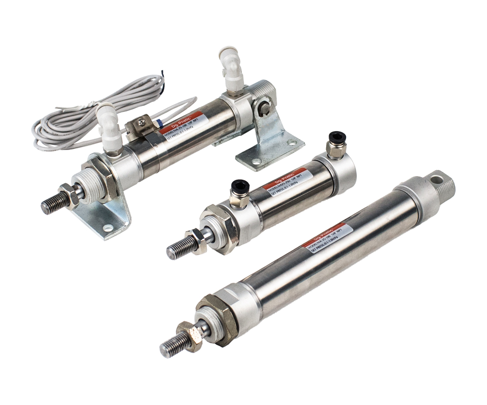
Bore Size(mm): 12mm~63mm.
Working Pressure:
 Double Acting Model: 0.15~1.0Mpa (22~145Psi) (1.5~10Bar)
Single Acting Model: 0.2~1.0Mpa(28~145Psi)(2.0~10Bar)
Proof Pressure: 1.50Mpa(213Psi)(15.0Bar)
Working Temperature ℃: -10~70℃. (No Freezing)
Cushion Type: Bumper/Air cushion
Standard Stroke(mm): 5 10 15 20 25 30 35 40 45 50 55 60 65 70 75 80 85 90 100~500mm
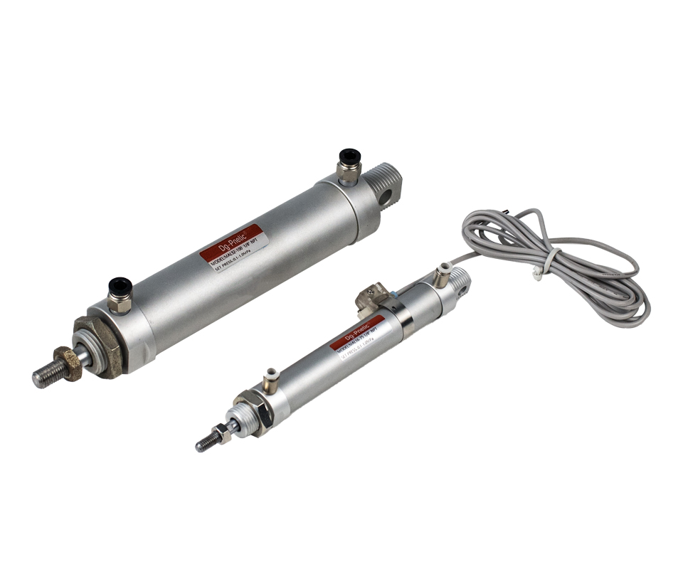
Bore Size(mm): 12mm~40mm.
Working Pressure:
Double Acting Model: 0.10~1.0Mpa (15~145Psi) (1.0~10Bar)
Single Acting Model: 0.2~1.0Mpa(28~145Psi)(2.0~10Bar)
Proof Pressure: 1.50Mpa(213Psi)(15.0Bar)
Working Temperature ℃: -10~70℃. (No Freezing)
Cushion Type: Bumper/Air cushion
Standard Stroke(mm): 5 10 15 20 25 30 35 40 45 50 55 60 65 70 75 80 85 90 100~500mm
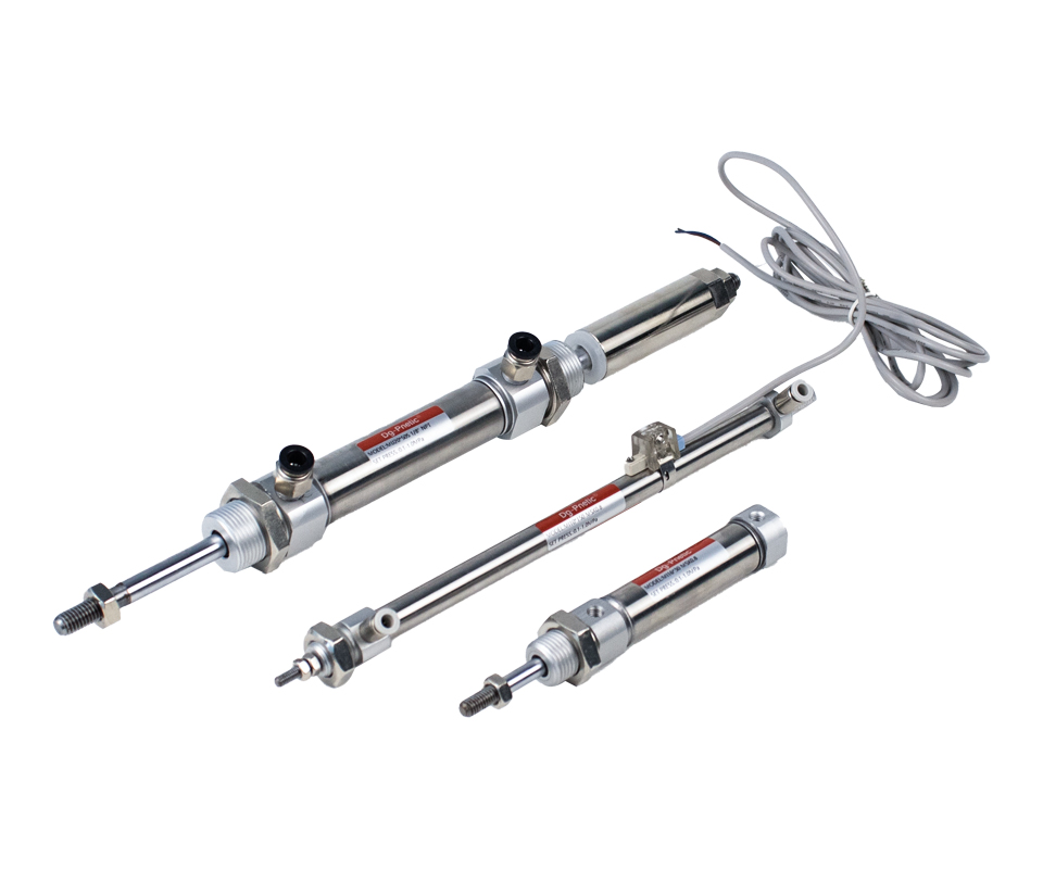
Bore Size(mm): 12mm~40mm.
Working Pressure:
Double Acting Model: 0.15~1.0Mpa (22~145Psi) (1.5~10Bar)
Single Acting Model: 0.2~1.0Mpa(28~145Psi)(2.0~10Bar)
Proof Pressure: 1.50Mpa(213Psi)(15.0Bar)
Working Temperature ℃: -10~70℃. (No Freezing)
Cushion Type: Bumper/Air cushion
Standard Stroke(mm): 5 10 15 20 25 30 35 40 45 50 55 60 65 70 75 80 85 90 100~500mm
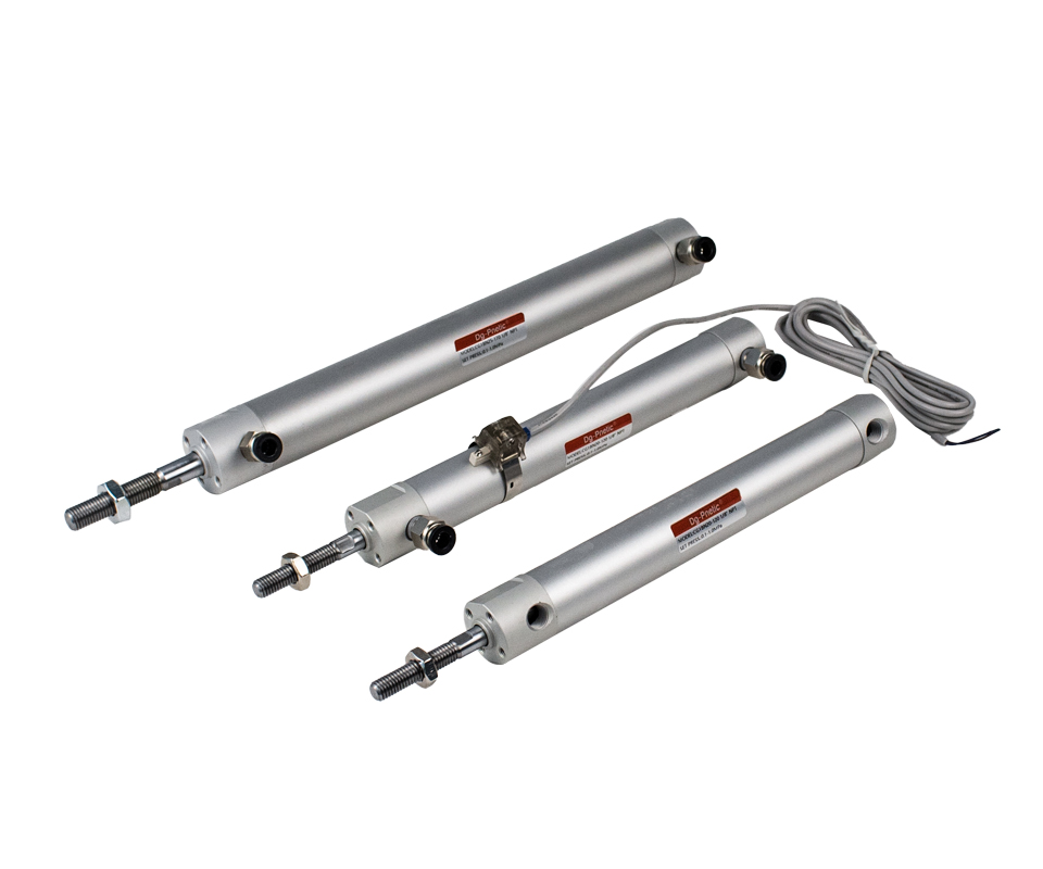
Bore Size(mm): 12mm~100mm.
Working Pressure:
Double Acting Model: 0.05~1.0Mpa (8~145Psi) (0.5~10Bar)
Single Acting Model: 0.2~1.0Mpa(28~145Psi)(2.0~10Bar)
Proof Pressure: 1.50Mpa(213Psi)(15.0Bar)
Working Temperature ℃: -10~70℃. (No Freezing)
Cushion Type: Bumper/Air cushion
Standard Stroke(mm): 5 10 15 20 25 30 35 40 45 50 55 60 65 70 75 80 85 90 100~1500mm
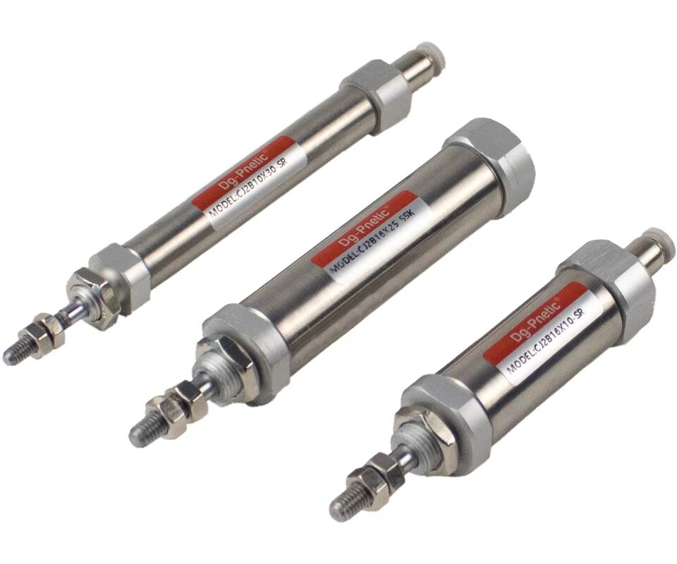
Bore Size(mm): 6, 10, 16
Working Pressure:
Single Acting Model: 0.25~1.0Mpa(35~145Psi)(2.5~10Bar)
Proof Pressure: 1.50Mpa(213Psi)(15.0Bar)
Working Temperature ℃: -10~70℃. (No Freezing)
Cushion Type: Bumper
Standard Stroke(mm): 5 10 15 20 25 30 35 40 45 50 55 60 65 70 75 80 85 90 100~200mm
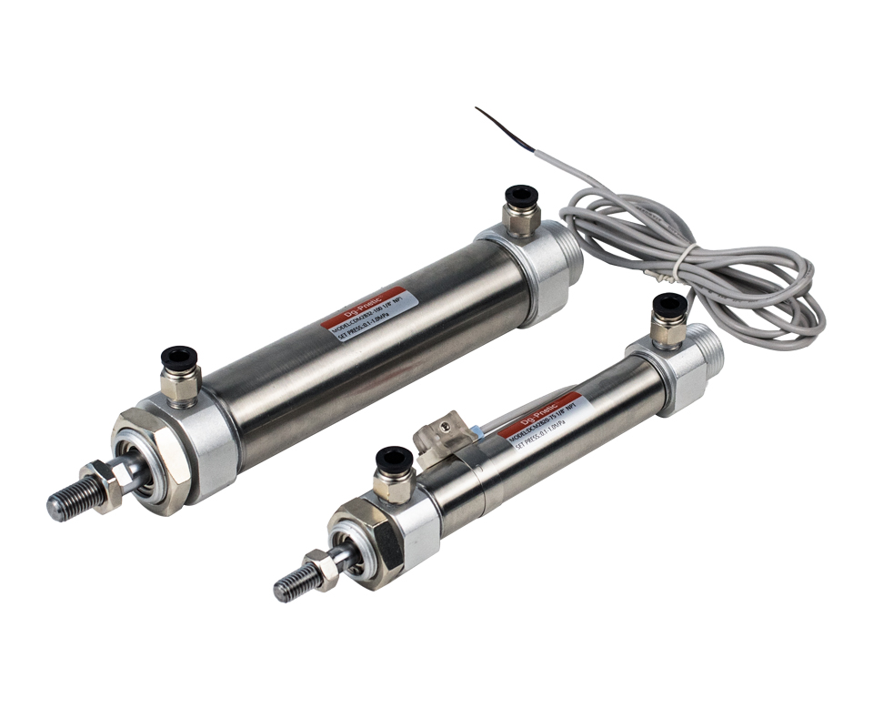
Bore Size(mm): 20mm, 25mm, 32mm, 40mm.
Working Pressure:
 Double Acting Model: 0.18~1.0Mpa (13~145Psi) (1.8~10Bar)
Single Acting Model: 0.23~1.0Mpa(17~145Psi)(2.3~10Bar)
Proof Pressure: 1.0Mpa(142Psi)(10.0Bar)
Working Temperature ℃: -10~70℃. (No Freezing)
Cushion Type: Bumper or Air cushion
Standard Stroke(mm): 5 10 15 20 25 30 35 40 45 50 55 60 65 70 75 80 85 90 100~250.
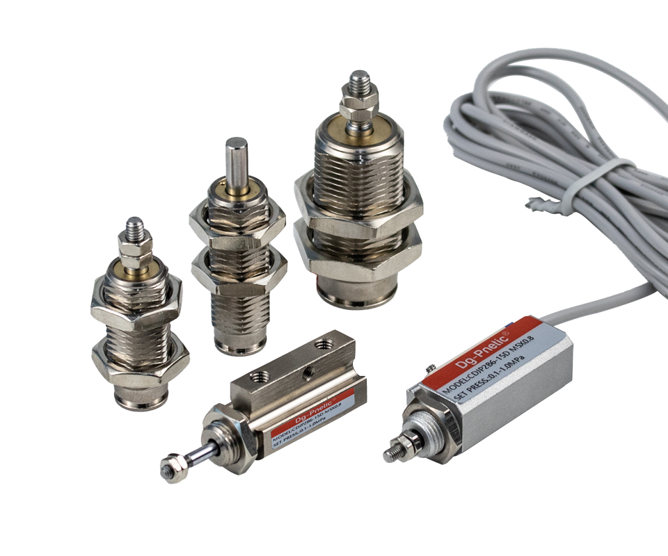
Bore Size(mm): 6mm, 10mm, 15mm
Working Pressure:
Double Acting Model: 0.1~0.7Mpa (7~98Psi) (1.0~7.0Bar)
Single Acting Model: 0.15~0.7Mpa(11~98Psi)(1.5~7.0Bar)
Proof Pressure: 1.05 Mpa(150Psi)(10.5Bar)
Working Temperature ℃: -10~70℃. (No Freezing)
Cushion Type: Not Required
Standard Stroke(mm): 5 10 15
Bore Size & CapacityMini Roundline Cylinders
Bore: ~½ to 1.5 in (12–40 mm)
Compact Cylinders (ISO 21287/CQ2 series)
Bore: from 12 mm up to 200 mm
 Compact cylinders support much larger bore sizes (up to 200 mm) than minis.
 Stroke Range
Mini Roundline
Standard stroke range: 1⁄16 – 12 in (1.5–300 mm), with maximums up to 12 in (300 mm)
Compact Cylinders
Designed for short to moderate strokes; long-stroke variants also available (e.g., CQ2-Z up to 300 mm)
Mini cylinders can achieve longer strokes, but extremely long strokes aren’t ideal for single-acting types.
 Acting Modes
Both types come in single-acting and double-acting configurations
For mini cylinders, long strokes (>300 mm) are usually used in double-acting setups.
Compact cylinders are optimized for short-stroke, reliable performance, especially in tight spaces (short travel but potentially large bore).
 Space Utilization & Shape
Both cylinders use a round barrel, but differ in dimensions:
Mini cylinders are longer and slimmer.
Compact cylinders are thicker but shorter proportionally, ideal for belted installation widths
Application fit:
Use mini cylinders where width/diameter is limited, but length is available.
Use compact cylinders for very tight-length installations with room for larger diameters.
 Quick Comparison
| Parameter | Mini Roundline | Compact Cylinder |
|---|---|---|
| Bore | 12–40 mm | 12–200 mm |
| Stroke | 1.5–300 mm (up to) | Short: ~up to 300 mm |
| Max Stroke | ≈300 mm | ≈300 mm (long-stroke variant) |
| Ideal Fit | Narrow width, long run | Short length, wider housing |
| Typical Use | Linear motion in slender layouts | Dense automation setups |
Which to Choose?Choose mini roundline cylinders when:
You need long-stroke motion in a narrow, slim profile.
Applications: linear transfer, ejectors, sliding systems.
Choose compact cylinders when:
You have a tight installation envelope lengthwise.
Need short-stroke actuation, and bore sizes up to 200 mm.
Applications: tight automation modules, fixtures, robotic end effectors.
Pressure Units ConversionTo calculate pneumatic cylinder force, understanding pressure units is essential. Here are common conversions:
1 MPa = 1 N/mm²
1 bar = 0.1 N/mm²
1 kPa = 0.001 N/mm²
1 psi ≈ 0.00689476 N/mm²
This means 1 MPa equals 1 N of force per mm² of area.
Force Calculation FormulaThe theoretical output force generated by a pneumatic cylinder is given by:
Where:
F = Force in Newtons (N)
A = Piston area in mm²
P = Pressure in N/mm² (i.e., MPa)
To convert diameter (D in mm) to area:
So the full formula simplifies to:
 Example Calculation
Calculate the force for a cylinder with a 32 mm bore at 1 MPa pressure:
r = D ÷ 2 = 16 mm
A = π × 16² ≈ 3.14 × 256 = 803.84 mm²
P = 1 MPa = 1 N/mm²
F = 803.84 × 1 = 803.84 N
Therefore, the cylinder produces approximately 804 N of force under 1 MPa
SummaryUse F = A × P where A = (π D²)÷4
Convert pressure into N/mm² (e.g., 1 MPa = 1 N/mm²)
A 32 mm cylinder at 1 MPa generates ~804 N of theoretical force